Recall that for a Shunt DC Motor, we have:
This implies that the speed of a shunt motor can be controlled in 3 different ways:
- Adjust armature resistance,
- Adjusting armature voltage,
- Adjusting flux,
Armature Resistance Control
Below we have a shunt motor with an adjustable resistor, , in series with its armature.
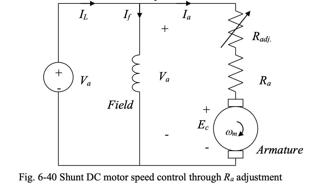
In a shunt DC motor, we have:
Since is constant, we have . Therefore, we have:
With , we would have:
This equation suggests that the torque-speed characteristic of shunt DC motor at different values are straight lines of different slopes, as shown here:
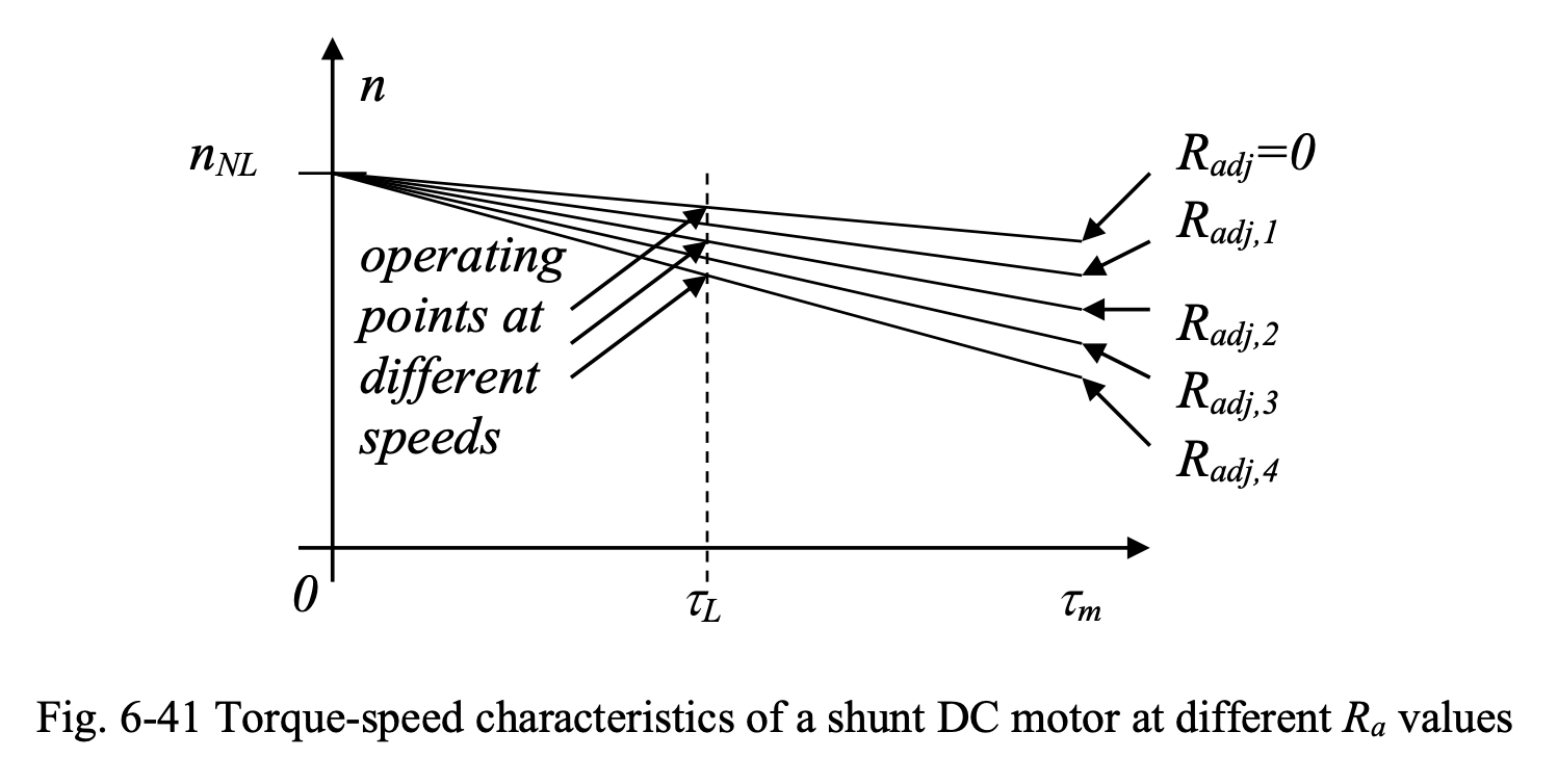
where . At any load torque , the motor can be operated at the desired speed by adjust .
This method of speed control is simple and inexpensive. However, the following disadvantages are associated with this approach:
- The controlled speed is always smaller than the speed without
- We cannot change the no-load speed of the motor
- There is an additional loss associated with
- Speed regulation is deteriorated, and the almost-constant-speed characteristic of shunt DC motor is lost.
Due to these disadvantages, this method is rarely used, unless the motor is operated at full speed (corresponding to ) most of the time.
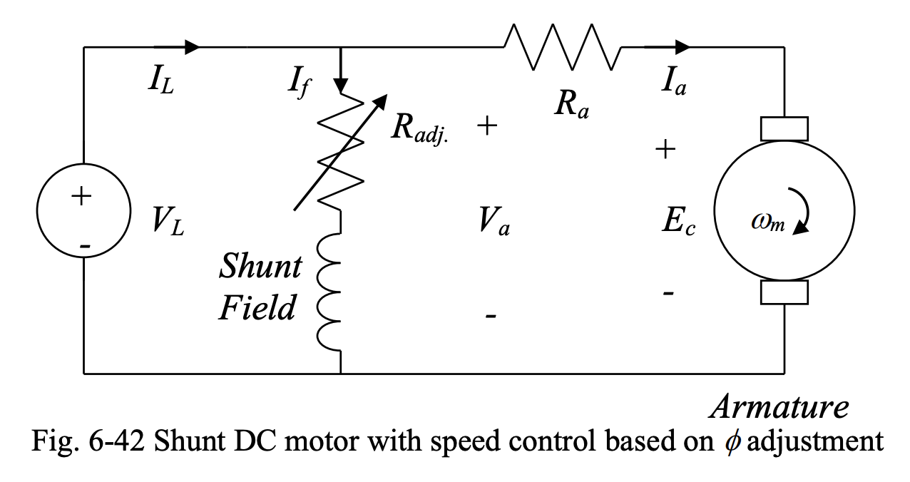
Field Current/Flux Control
Shunt DC motor speed can be controlled by adjusting through varying , using an adjustable resistance in series with the field circuit. This is shown below.
Since appears in both terms on the right side of
the effect of varying on speed is not obvious from the inspection of the formula. However:
- As decreases at a given , increases.
- As increases at a given , decreases.
The plot below shows the torque-speed characteristics of a shunt DC motor for two different values of :
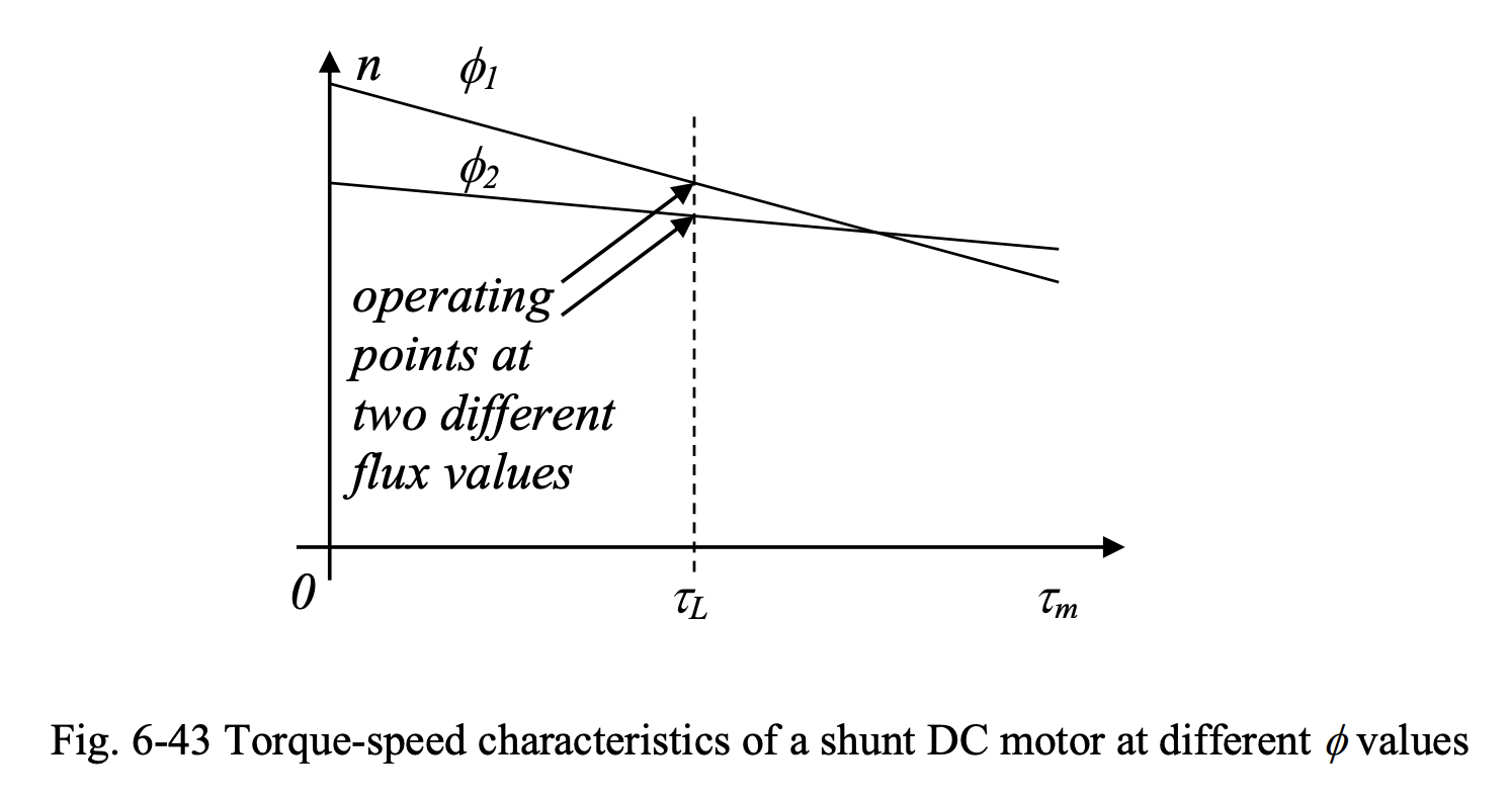
where or . In electric machines terminology, decreasing to go from a lower speed to a higher speed is called field weakening.
Let’s go through the process of increasing the motor speed by decreasing , step-by-step. First, assume steady-state operation (constant motor speed).
- Increasing means that is increased.
- Since we have , decreases.
- Thus, the flux also decreases because .
- Decreasing flux also means decreasing counter emf because .
- This in turn results in a higher armature current, .
- Higher armature current also means higher torque, .
- Note that even though decreases, the increase in dominates and results in increasing. In fact, a small change in , results in rather large changes in and .
- means that increases, because .
- Then, the counter emf must increase because .
- Note that even though decreases, the increase in dominates and results in increasing.
- Thus, armature current decreases because .
- decreases because .
- has been is reached at a speed higher than the original speed. This will be the new steady-state speed.
The advantages of the field flux control of shunt DC motor speed are:
- It is possible to change the no-load speed.
- Speeds higher than the one corresponding to can be obtained.
The disadvantages of this method of DC motor speed control are:
- Speed regulation (i.e., slope of speed-torque characteristic) is affected.
- Extra losses will occur due to the presence of .
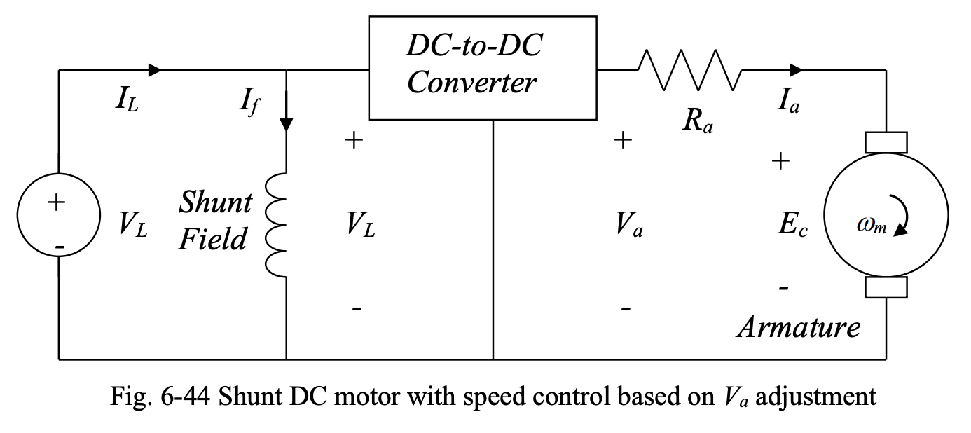
Armature Voltage Control
Below we have the schematic diagram of a shunt DC motor with speed control based on armature voltage adjustment. A constant voltage is used to produce a variable voltage using a DC converter.
The torque-speed characteristic of a shunt DC motor based on
is shown below for three different armature voltage values:
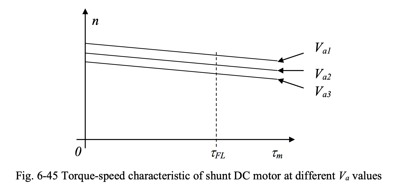
where we have .
The sequence of events in this method of control, when armature voltage is increased, is as follows:
- is increased by the DC/DC converter.
- As a result, increases since we have .
- The produced torque increases as well as we have .
- Since , the speed increases.
- In response to this, counter emf increases with .
- Thus, decreases since we have .
- The produced torque decreases with
- We have (steady-state) reached at a speed higher than the original speed. This will be the new steady-state speed.
Advantages:
- Speed control at any loading level, from no load to full load, is possible.
- losses associated with armature resistance control and field resistance control methods are avoided.
- The close-to-constant-speed characteristic of shunt DC motor is maintained.
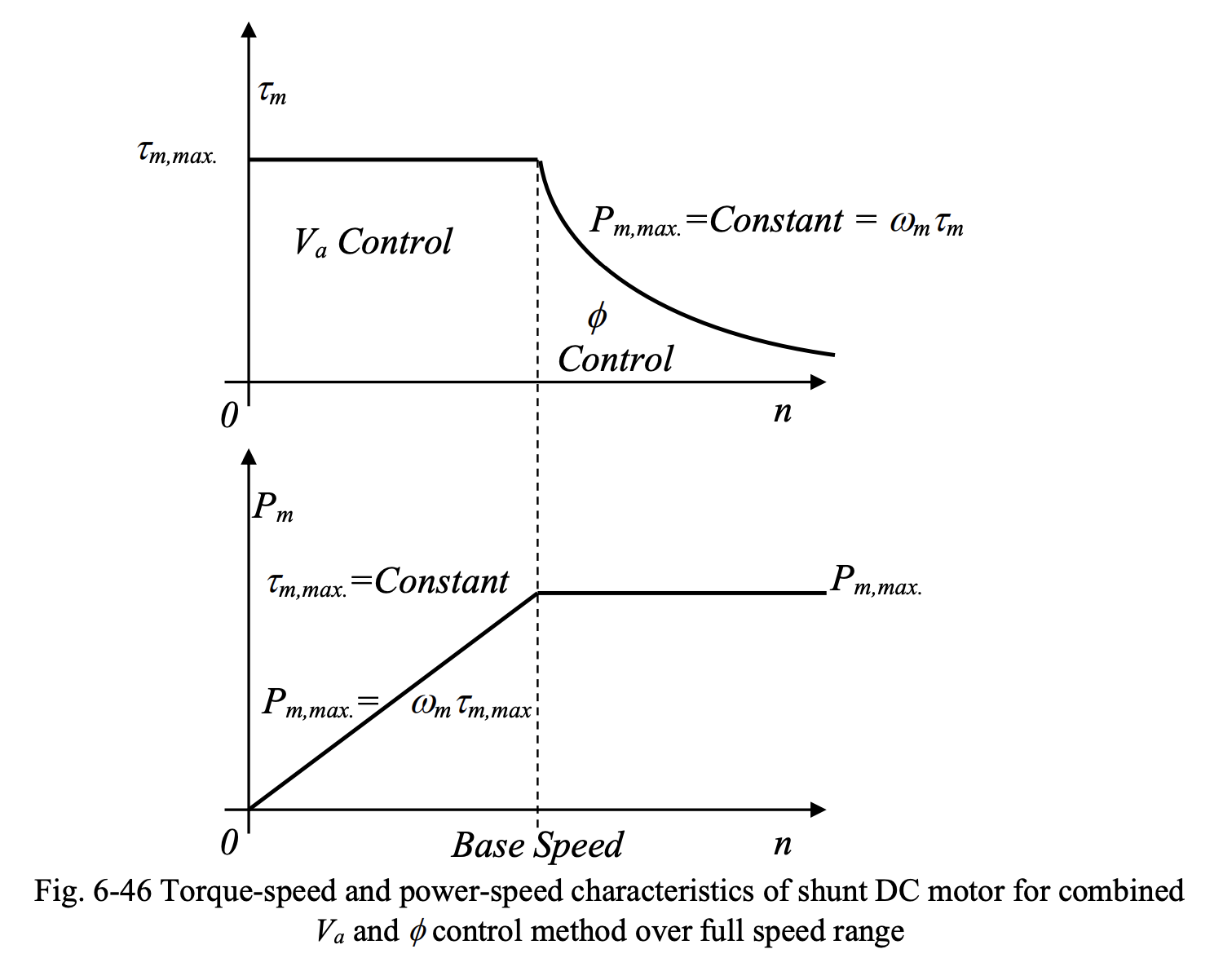
Full Range Shunt DC Motor Speed Control
Armature voltage control and field current control are the two most common techniques for shunt DC motor speed control. Each of these two methods has a range of safe operation.
Armature voltage control can be used to control the speed of the shunt DC motor from standstill to a speed called base speed that corresponds to rated terminal voltage, rated power and rated field current. If a higher speed is desired, it cannot be obtained by increasing armature voltage beyond the rated value, as this will not be safe.
Field flux control can be used to increase the motor speed by decreasing and (i.e, field weakening). The minimum speed that can be obtained by field flux control method corresponds to the rated field current. The minimum speed in field flux control method coincides with the maximum speed in the armature voltage control technique, i.e., the base speed.
To combine the best of the two methods, the shunt DC motor is controlled by armature voltage control between zero speed and base speed, and by field current (or field flux) control beyond base speed. This is illustrated below.
Examples
Example 6-5
Example 6-6