Below we the schematic diagram of a shunt DC motor and its equivalent circuit diagram.
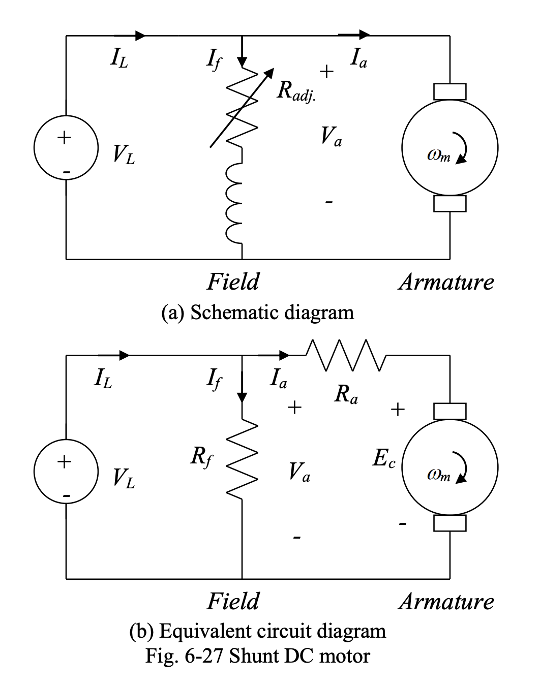
In shunt DC motors, the field circuit is connected in parallel with the armature circuit, and both circuits are fed from the same DC voltage source. The resistance in (b) is the combination of the field resistance and an adjustable resistance, which is used for speed control purposes.
The main relations for this type of motor are:
where is the number of turns of field winding and is the magnetic reluctance.
Then:
Thus, if is constant, .
Speed-Torque Characteristics
Consider the equivalent circuit diagram of the shunt DC motor shown below.
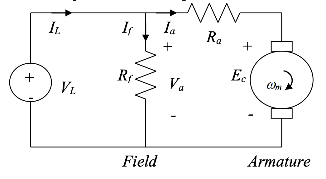
We have:
Using
we have:
Then, we have
The rotor speed can be found from above as:
This means that plotted as a function of is a straight line, provided that is constant:
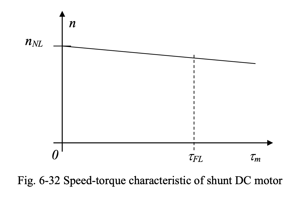
Thus, the speed of a shunt DC motor drops under load. This drop, however, is limited to below 8% of the rated speed, from no load to full load. Shunt DC motors are well-known for their fairly constant speed under load.