Switch mode DC/DC converters are commonly used in regulated DC power supplies, DC motor drives, interface of battery energy storage systems with DC bus, maximum power point tracking of solar PV systems, and in any applications requiring DC voltage scaling.
They are categorized as:
- Step-up or step-down based on whether they upscale or downscale voltage
- Unidirectional or bidirectional based on direction of power flow
- Non-isolated or isolated (based on lack of or existence of isolation between the two sides)
Control
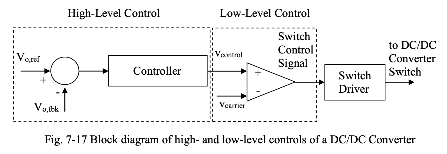
In DC/DC converters, the objective is to control the average value of the output voltage based on a control signal. There are two levels of control involved: high level and low level.
In high-level control (which is closed loop control), the measured output voltage signal is compared with a reference signal and the error is amplified in a controller to generate a control signal.
In low-level control, the control signal produced by the high-level control is converted to a switch control signal using a modulation technique. The switch control signal will be applied to the switch through a switch driver circuit. The switch driver amplifies the switch control signal and outputs an ON/OFF control signal that matches the type of switch (voltage-controlled switch or current-controlled switch). The isolation between the control circuit and power circuit is also provided by the switch driver (usually through light, using an optocoupler).
A very common modulation technique for DC/DC converters (as well as other converter types) is Pulse Width Modulation. In PWM, the control signal is compared with a repetitive piecewise linear signal (usually a triangular signal), called carrier signal, of certain amplitude and frequency, to generate the switch control signal.
Fig. 7-17 shows the block diagram of high- and low-level controls of a DC/DC Converter.
See: