PWM is a technique used to control the power or intensity of a signal. It allows us to easily convert a digital signal to create an analog voltage, so that we can control analog outputs using digital pins without using a DAC. Microcontrollers typically have built-in support for PWM outputs but not necessarily DACs, since this is cheaper in terms of hardware and has noise immunity.
The average value of the signal over time is . This is also the zero-frequency components of its frequency spectrum, so a Low-pass Filter (LPF) can extract this DC offset voltage.
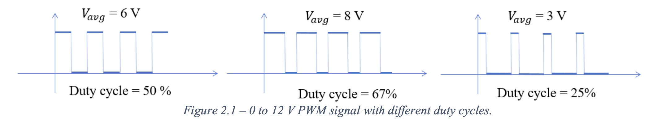
In simple terms, PWM rapidly turns a signal ON and OFF at high frequency. The average power or voltage can be controlled by adjusting the ratio of the ON time (pulse width) to the total period.
- Applications: motor speed control, power regulation, audio amplification, dimming LEDs.
- It’s far more efficient to drive transistors fully-on/full-off (digital) instead of partly on (analog). However, this can be very noisy due to high frequency switching.
- We can encode information in PWM parameters, like duty cycle.
Averaging the digitally-generated PWM signal provides an analog voltage that can be varied by changing the duty cycle. In Lab 2, we use the signal generator to generate a PWM signal and control the output to change the duty cycle and frequency.
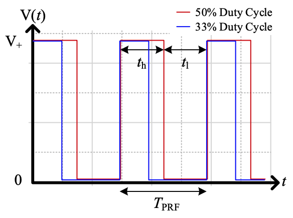
Pulse repetition frequency (PRF)
Frequency of rectangular waves, defined as:
where , such that:
- is the duration of time that the signal is high ()
- is the duration of time that the signal is low ()
The PRF is usually much higher than the intended frequency of the resulting analog voltage output signal.
Duty cycle
Proportion of time the signal spends high, expressed in percent. Given by:
Ripple
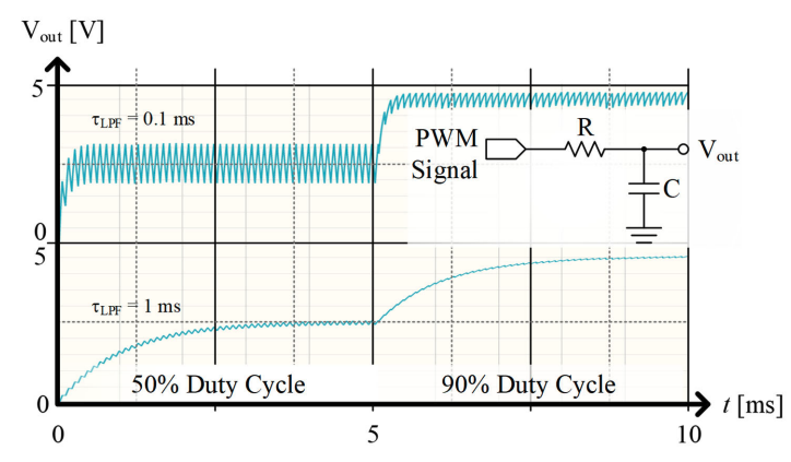
Ripple refers to slight variations in the DC average voltage value due to the fact that there is some time required for the LPF to “react” to the voltage. This is like an RC time constant; in fact, the simplest form of a LPF uses a capacitor.
There is a fundamental trade-off between response to change in duty cycle and ripple.
- A larger time constant will produce a signal with less ripple. However, a larger constant will also mean that slower reaction to a change in duty cycle (and thus output voltage).
Two different time constants – the loser one has far more ripple but reacts faster:
Example Question
Design a PWM circuit driven by a 0 to 3.3 V digital output that uses an NMOS and RC filtering to create a precision reference voltage from 0 to 12 V. Assume that you have a +12 V rail and an op-amp available for buffering. The response time to a change in duty cycle should not exceed 100 ms.
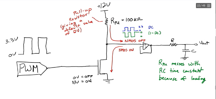
If , .