At the highest level, the DAC is a black box that takes in a reference voltage, , and scales it by both a proportionality constant, , and the binary value, , to produce an analog output signal, such that:
where
- is the output
- is a proportionality constant
- is the reference voltage
- is the binary word.
We will use . This means that the maximum output voltage will be:
therefore it will always be smaller than .
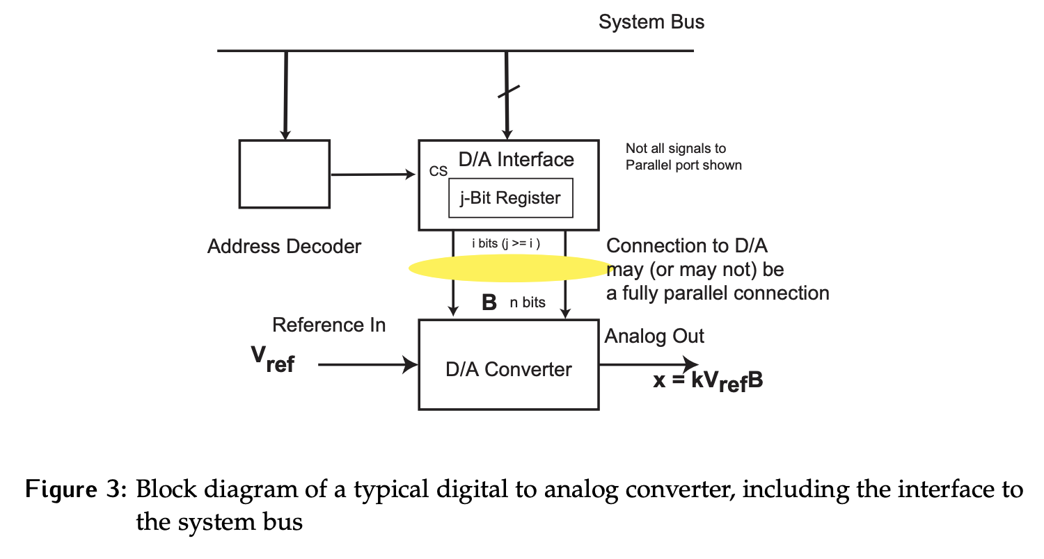
The binary value can be provided to the DAC in either serial or parallel form; either way, a parallel port is used to provide a connection to the system bus, thus providing a path for the CPU to set the binary value by writing to an interface register .
Generic block diagram of a DAC:
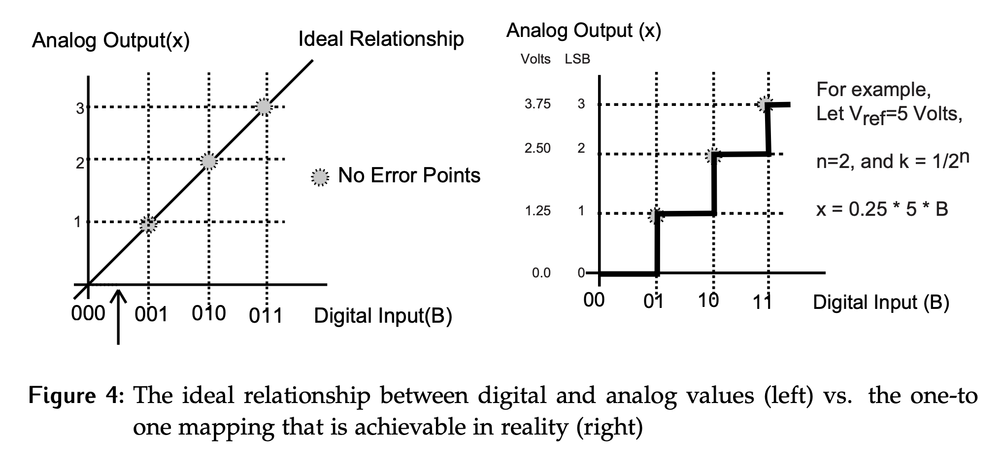
Quantization and LSB
Analog signals are continuous, digital signals are discrete. As such, for digital values, we can only produce outputs at points along the analog range, ideally at equally spaced intervals. Those intervals, or steps between outputs, are 1 LSB each.
For example, if we have , , , the only analog outputs that can be produced are:
where is an integer between 1 and 3. While was , the maximum output that can be produced is , which is exactly LSB less than . For the converters considered in this course, will always be 1 LSB less than of .