Computers rarely monitor signals that do not change. A changing signal may cause problems for DAC and ADC converters.
- Example: Consider the successive approximation ADC – what would happen to the output if was not constant while the successive bits are tested?
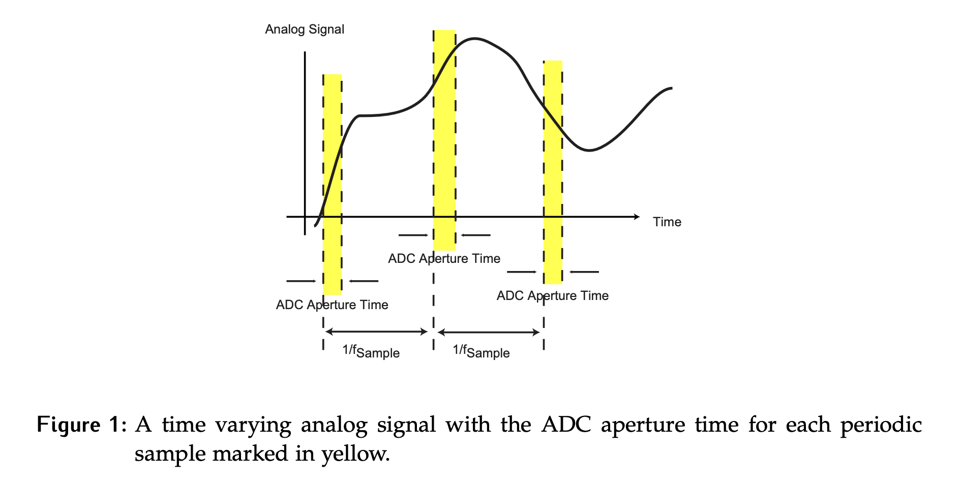
The converter aperture time is the time that the converter output (result) is sensitive to changes in the analog signal. If the analog signal changes too much during this time, the output may be garbage.
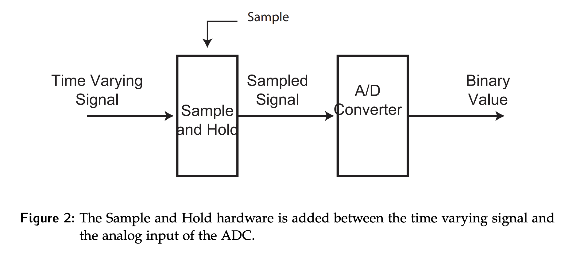
The solution is to add a sample and hold (SH) circuit to the system, shown below in simple block diagram form. The time-varying signal, which was when ADC designs were considered, is fed into the sample and hold circuit. The output of this circuit is a sampled signal that meets the requirements to remain stable throughout the converter aperture time.
For the ADC designs that produced persistent data, the timing of the sample signal that controls the SH hardware is relative to the timing of start of conversion (SOC) and conversion complete (CC) on the ADC as shown in Figure 3.
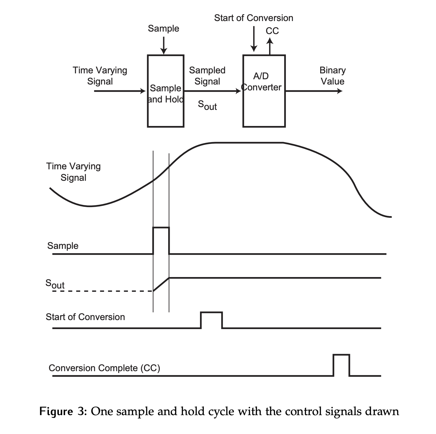
The sample must take place before the conversion starts.
- While the sample signal is high, the output of the SH circuit will track the time varying input signal.
- When sample is low, the value at the output is held stable.
For each ADC, it is necessary to consider where the conversion actually begins. Is it on the rising or falling edge of SOC? This will determine where must be stable for proper operation.
Converter Input Signal Frequency
A sample-and-hold circuit is often used to ensure that the ADC input signal does not change during the converter aperture time. The frequency of a periodic signal impacts the required sampling rate. In order to see why a sample and hold circuit is often required, consider the following scenario: What is the maximum frequency () of a time varying signal that can be sampled without adding a sample-and-hold circuit?
In order to calculate this, we need to make some assumptions:
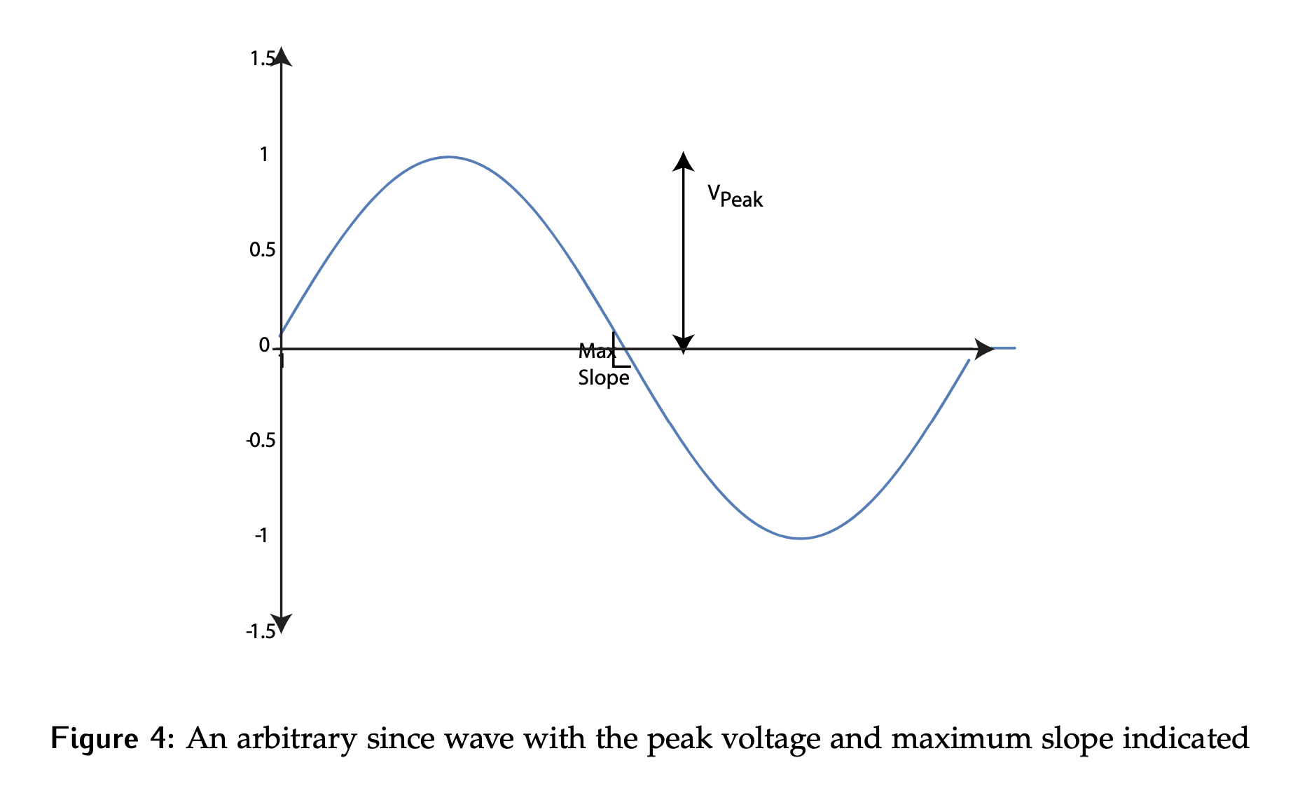
- The signal is a sine wave of fixed frequency, which means that the worst case change in signal value during a fixed time period will occur at the point of maximum rate of change.
- is half of the amplitude of the sine wave.
- We assume that the signal must change by no more than (0.5 divided two to account for sampling rate) while the conversion is taking place.
Then, we have:
Suppose that a 12 bit converter is used and that it requires 10 microseconds to convert a signal in the range of 10 V peak-to-peak (i.e., ). This means that the converter aperture time is 10 microseconds. The amount that the input can change in is 0.25 LSB.
What does this correspond to in terms of voltage? We have:
Thus, there can be at most change in (at the steepest slope).
This gives us:
For this system, without a sample-and-hold circuit, we are limited to a input signal, despite a converter! This is a very typical converter speed, but is very slow compared to real-world signals. Something needs to be done, and making the converter itself faster is not a practical solution as there are limitations to how fast the internal devices can operate. A better solution is to add hardware to hold the input value seen by the converter stable throughout the conversion time.
See here for how sample and hold circuits can be implemented.