Analog-to-digital converters take an analog input and produce a digital output.
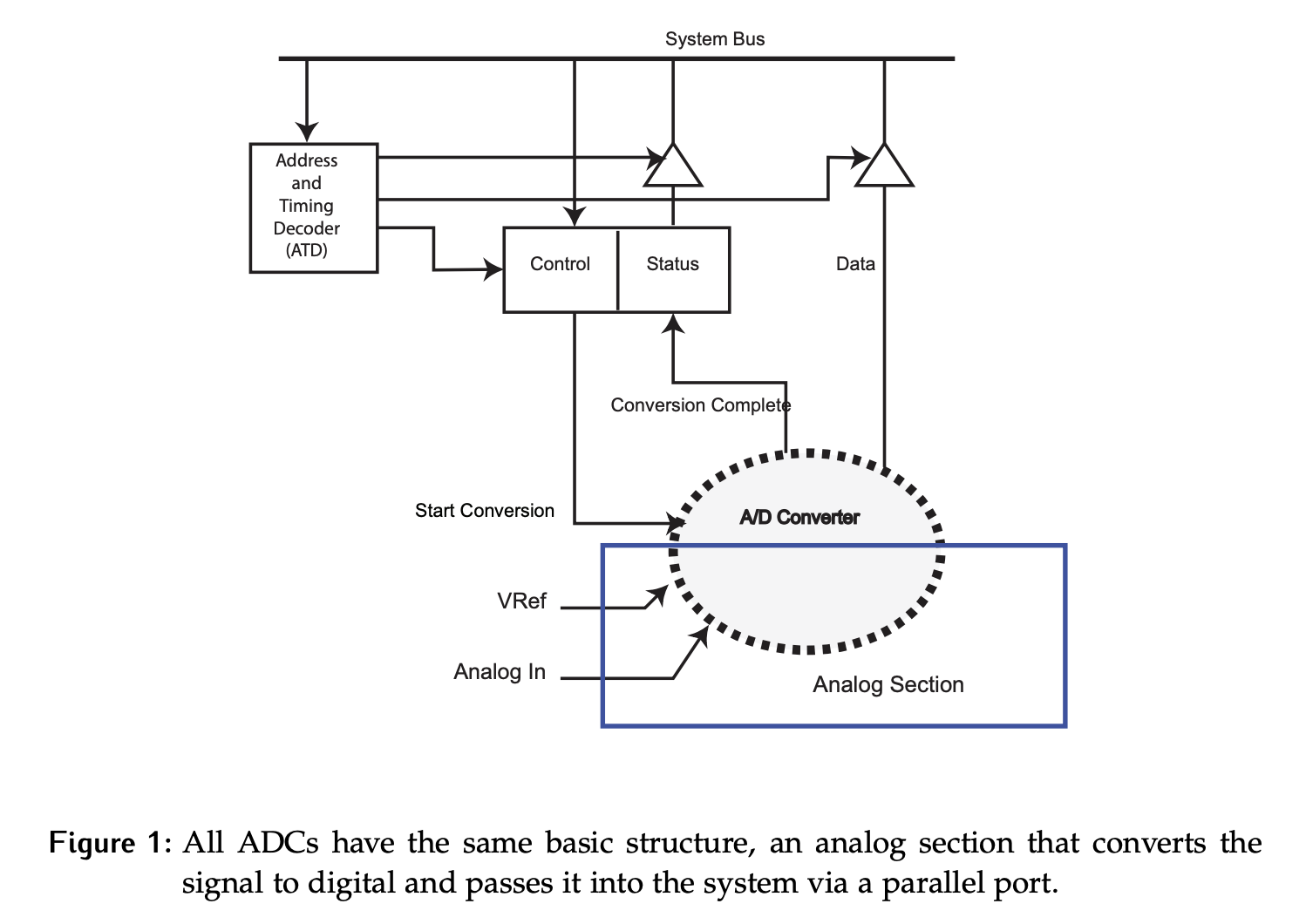
ADCs all have the same general structure shown below:
- The top half of the diagram is just a parallel interface connecting peripherals to the system bus in the microcontroller.
- In the converter itself, there are some analog pieces of hardware that take in the and an analog signal then bridge to the digital side.
- For two of the designs we will look at, the converter will use a
Start Conversionsignal from theControlregister in the parallel interface and set a bit calledConversion Completein the Status register when it is done. - Because the conversion only takes place when triggered by the start signal, the resulting digital value will be persistent and no additional register in the parallel interface is required to hold the data.
- Another way to think about this interaction between the CPU and the ADC is to classify it as a consumer responsive scenario: data will only be produced when the consumer asks for it.