The binary weighted resistor ladder DAC implementation based on op-amps in a summer configuration.
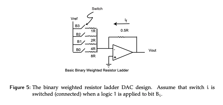
The voltage across each of the resistors in the summer is set to be the same, but the resistances themselves are set to powers of 2, because this reflects the weighting of each bit in a binary number.
- If the bit in the LSB position contributes 1 to the total, a bit one position to the left should contribute double that and so on. In the case of this summer configuration, currents are scaled accordingly.
- The largest resistor will contribute the smallest amount to the total current at the inverting node, while the smallest resistor contributes the largest amount.
- Note that each possible current is multiplied by a corresponding bit . If that bit is a 0, the corresponding switch is open and no current is contributed by that resistor.
We can find an expression for with nodal analysis, then rearrange it to find a relationship between the binary input value and the output voltage .
- To calculate the maximum output, all bits would be on, so the summation of is equal to . Re-arranging this gives an expression for the full scale analog range.
Consider the previous definition of an LSB in terms of an analog output:
- It’s important to remember that the only reason the scaling factor is is because the feedback resistor has a ratio of . If this resistance was modified, the relationships developed here would no longer hold.
- Also, is technically negative; in most cases, it’s desirable that the output of the DAC have a positive range, so we need a negative to cancel the negatives.
Constant Impedance Implementation
DACs are not built with switches as shown above. For the device to work properly, has to remain constant. It’s very difficult to keep a constant voltage reference when the current draw is changing drastically, as is the case here when the current depends on which bits are enabled. This can be fixed by modifying the switches to single pole-double throw (SPDT) switches, as shown below in Figure 6.
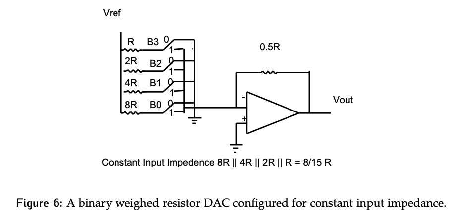
- One throw is still connected to the inverting node of the amplifier, but the other is connected to ground. Recall that the inverting node is also at .
- As a result, regardless of which position the switch is in, the same current is passing through the resistor. However, the current might just flow to ground instead of the op-amp terminal if the switch is at position 0.
- Since the current through the resistor is always the same, the current draw from perspective never changes.
- In other words, the input impedance is constant.
- The downside of this is that its very power inefficient as the max possible current is always being drawn, whether that current is being dumped to ground or is actually going to the op-amp node
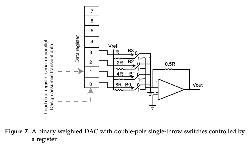
Consider the connection between the binary data stored in the register and the DAC as shown in Figure 7. It’s important to notice that the binary values are controlling the position of the switch, they are not connected directly to the current path.
Resistor and Current Issues
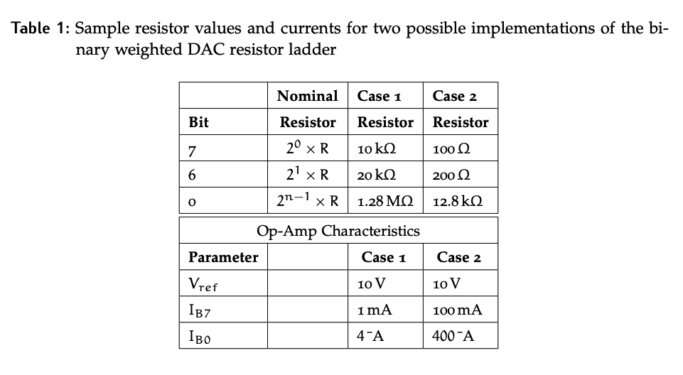
One problem with the original design was solved by stabilizing the current draw on . Now consider some additional issues by looking at a more realistic 8-bit DAC, and the resistor range required for this.
If a is chosen for bit 7, which is the smallest resistance because we want to reduce the overall current draw, then a resistor is needed for the lowest bit. This is a huge range; a typical resistor tolerance will have on the current accuracy in the summer. Another challenge is the fabrication of this broad range of values; they are often done with different materials, so they may age differently or have different thermal coefficients, further impacting the accuracy of the DAC.
There is also an op-amp issue. If large resistor values are used, an op-amp that can handle a current range of to is needed, which is extremely low and below the noise floor for cheap op-amps. If smaller resistors are used, we can get a minimum current flow of , which is more realistic; however, the max current is now , and that’s just for turning on the MSB. If we want to turn all bits on, the current will be almost . Getting an op-amp to handle this range means an expensive device; for larger values of , even larger resistors will be needed, further increasing the required current ranges.