From the CPU perspective, addressing is easy, we just load a value into the MAR. But how does a device recognize its addresses?
Devices are addressed in an embedded system by assigning ranges to devices, based on how many unique addresses each requires. These assignments are summarized in a table known as the address map, which can be found in microcontroller documentation. The address of a particular register is specified using a base address for the device, and an offset from it.
Memory will require a large number of address, in many systems taking at least half of the available address space, while a device interface only requires a handful of addresses, generally less than 10. The addresses assigned to each device will always be sequential.
Address Decoding
There are two common ways to decode addresses on the system bus: centralized and de-centralized. Decoding here means that we are translating an address into a selection signal that activates the appropriate device on the bus. This way, only one devices responds on the bus at any given time, avoiding conflict.
Centralized Address Decoder
In the centralized scheme, a separate block of logic is used to select the active device. Each device only needs one line, commonly known as a chip select or enable, that tells it it is participating in the current transaction when activated.
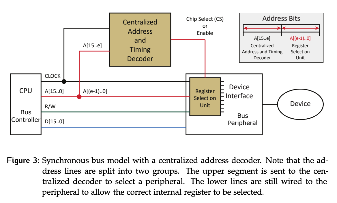
Notice that the address on the address line is split into two groups:
- The lower bits are still fed directly to each device. These are used to determine which of its internal registers is to be accessed when the corresponding chip select/enable is set.
- The upper lines are fed to the centralized decoder.
For example, if we were given the address 10100101:
- The centralized decoder uses
1010to select Device 10 by activating its chip select line. - Device 10 recognizes that its chip select line is active.
- The lower bits
0101are used by Device 10 to access internal register 5.
Where the split is depends on how many registers are inside the devices. The upper bits fed to the centralized decoder must provide a sufficient amount of information for each of the devices it supports to be uniquely identified.
De-centralized Address Decoder
The de-centralized scheme requires each device to have the hardware to check the full address and control information for themselves.
Comparison
From a logical perspective, there is little reason to use centralized decoding but it has several physical advantages:
- The centralized decoder is placed close to the CPU on the chip, so the majority of the address lines only need to be run a short distance.
- By combining the logic to check for address of all devices in one component, overlapping sections can take advantage of common gates, whereas each device needs its own copy of the hardware in the decentralized case.
- A device with address in the range of
0x1200can share a good portion of the combinational decoder logic with a device whose address is in the0x1208range.
In reality, most microcontrollers use a combination. Centralized addressing is typically not used with memory, as the large number of associated addresses make the benefits moot. Devices tend to share a centralized decoder; since each device only has a small number of registers, we just need enough lines to select between them to be run right to the device.
- For example, if a device has 6 internal registers, the lowest 3 address lines must be run to the device. To calculate the number of lines needed, recall that .