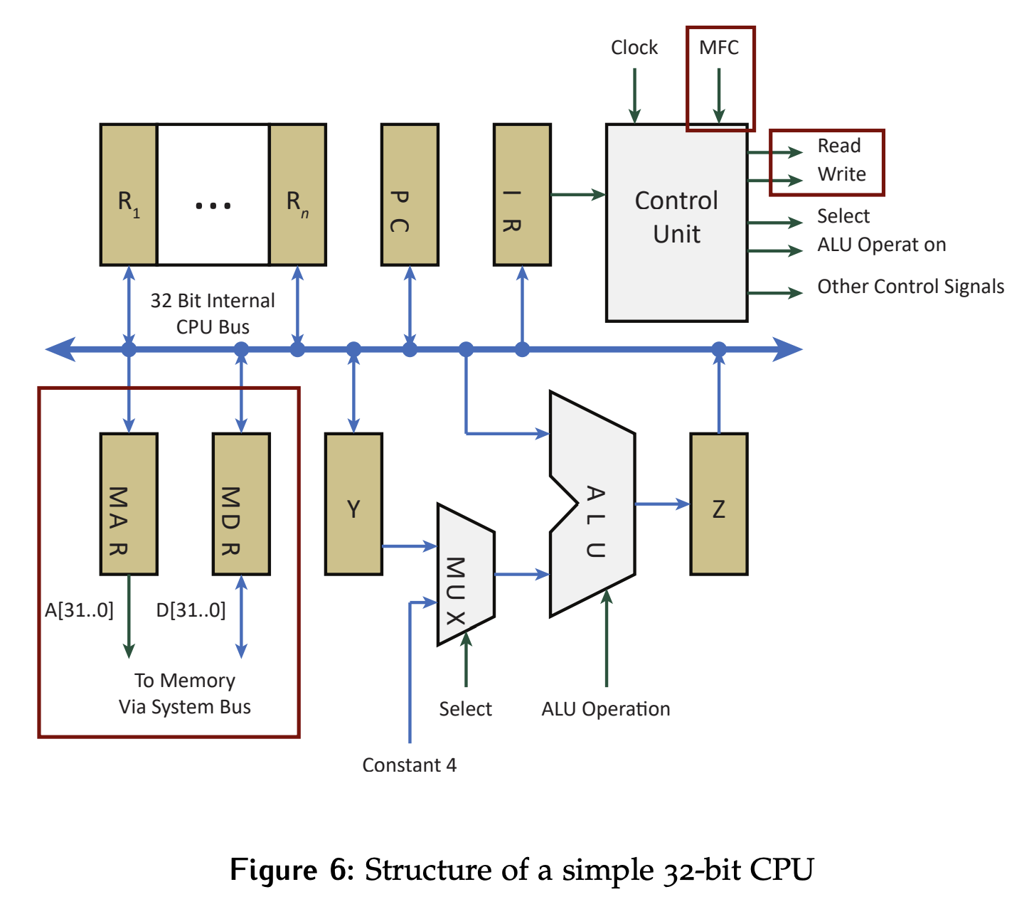
CPU Architecture
A Central Processing Unit (CPU) is composed of the following:
- Arithmetic and Logic Unit: Performs operations required by instruction sequence.
- Control Unit: Interprets instructions and generates a sequence of operations.
- Registers: Store the state of the system:
- General purpose registers: Provide internal storage for intermediate results
- Special purpose registers: Store control/status information
- Program counter (PC): Stores the address of the next instruction to read.
- Instruction register (IR): Stores the next instruction
- Program status register (PSR): Stores the processor status (flags, etc.)
- Stack pointer (SP): Stores the address of the top of the stack
- Memory address register (MAR) and Memory Data Register (MDR): Buffer data between the CPU and the memory via the system bus.
MAR and MDR Registers
The MAR and MDR are of particular interest. The control unit signals MFC, READ, and WRITE work alongside these registers to control the system bus and tell memory or peripherals what to do.
- The MAR holds the address of the memory location that is to be accessed (read from or written to). When you want to read data from memory, you place the address of the data in the MAR.
- The MAR is unidirectional. It can only be written to by the internal CPU bus and can only be read by the external system bus. It will contain the address of the memory location to be accessed by a system bus transaction
- The MDR holds the data that is being transferred to or from memory. For a read operation, after the memory retrieves the data from the address specified in the MAR, it places that data in the MDR. For a write operation, the data to be written to the memory location (addressed by the MAR) is placed in the MDR.
READ and WRITE signals
READ and WRITE are control unit signals that tell the memory what type of transaction is being executed. With this, the memory knows whether to return the data from location addressed by the MAR (read) or save the data to the location addressed by the MAR (write).
MFC signal
MFC (memory function complete) is an input to the control unit. This is the only signal driven by memory. It serves as a mechanism for the memory to acknowledge the requested action has been completed.
- For a read transaction, it would signal that the requested data is now available at the D-input of the MDR. For a write, it is used to signal that the data has been saved to the requested location.
- For a write, it is used to signal that the data has been saved to the requested location.
- This signal does not have to be a physical wire. Instead, it can be implemented virtually, meaning something else in the system can be taken as the acknowledgment of these actions. For synchronous buses are studied in detail, a clock edge is used to fulfill this function.
Operation Logic
Recall that read and write are from the CPU’s perspective.
The MDR must allow both the internal CPU bus and the external system bus to read and write from it without creating conflicts. This is done by adding some additional logic to the input and output of the register as shown below.
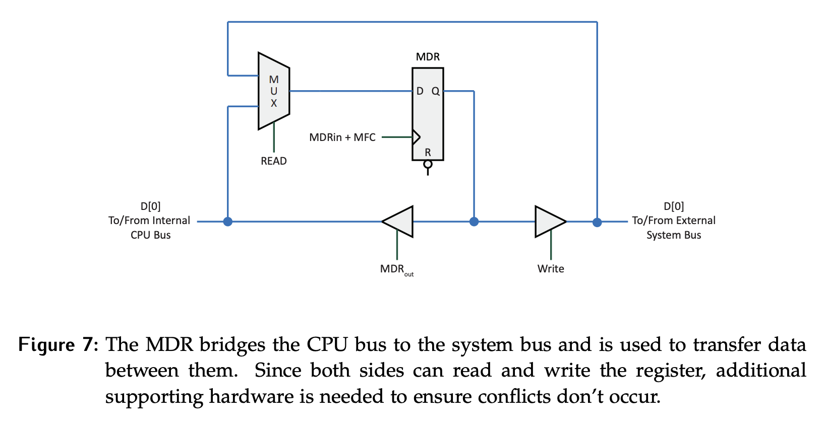
For a write transaction, the information needs to be transferred from the internal CPU bus, into the MDR, then to the external system bus.
- This routing requires that the READ signal be a 0 to make the information from the internal system bus available at the D-input of the register.
- A rising edge on the
MDR_insignal will load the data into the MDR. - When the system bus is ready to complete the write transaction, the WRITE signal will be set to 1, making the value available on the external system bus.
For a read transaction, information needs to be transferred from the external system bus, into the MDR, and then to the internal CPU bus.
- Setting the READ signal to 1 will make the data from the external bus available at the D-input of the MDR. In this case the MFC signal will be used to clock it in.
- When the CPU is ready for the data on the internal bus, it will set
MDR_outto 1, making the data available on the internal CPU bus.