An alternative system bus architecture is the asynchronous implementation. This bus no longer needs to use a clock to control timing and synchronization between the sides. Furthermore, we can allow the speed of each transaction to vary, which means we are not necessarily limited to the slowest device in the system.
The major difference in our asynchronous bus model, shown below in the block diagram, is that there is no longer a clock signal. Instead, the controller and peripheral signals are used to synchronize the transaction.
- The CPU is the only controller in our system, so it drives the
controllersignal - The
peripheralsignal is driven by whichever peripheral is involved in the transaction
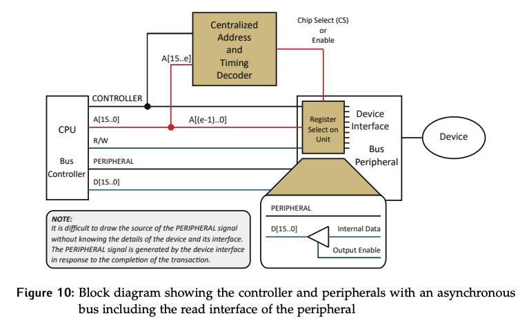
First, a tri-state is needed between the data source and the data lines of the bus, ensuring there are no conflicts on the data lines.
Since we no longer have a clock to control the timings, the letters through will be used to indicate important time points in the transaction.
This model is sometimes referred to as fully interlocked asynchronous. “Fully interlocked” comes from the cause-and-effect dependency between the assertions and de-assertions of the controller and peripheral signals.
- The assertion of
controllercauses the assertion ofperipheral - The assertion of
peripheralcauses the de-assertion ofcontroller - The de-assertion of
controllercauses the de-assertion ofperipheral
Read Transaction
The transaction starts with both the controller and peripheral signals de-asserted. The terms asserted de-asserted are used instead of high and low, because these two signals can be used as either active high or active low.
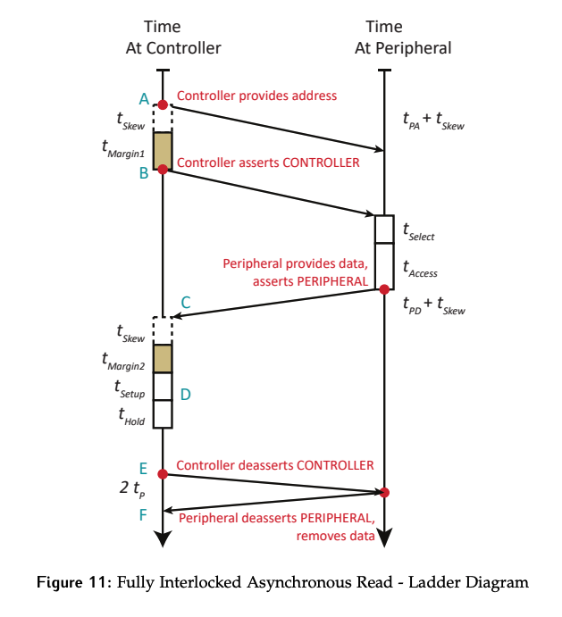
The read transaction begins at time point with the controller driving the address on the bus. It will take for the address to reach the peripheral and be settled. After the controller sets the address, it will wait for and some margin before asserting the controller signal.
- Why only wait for ? Because both the
addressandcontrollersignals will take time to propagate to the peripheral, but only the address will suffer from skew.
The controller signal has essentially replaced the falling edge of the clock from the synchronous model. When the controller signal is seen to be asserted at the peripheral, it signals that address and control are valid and can be acted. As such, the margin is included between asserting the address and controller signals.
Once the centralized address decoder or peripheral has seen that controller has been asserted, the address is checked to identify the peripheral involved. Thus, the time takes place with the same actions as in the synchronous model. It’s followed by the access time, .
At the end of , the peripheral drives the data on the lines and it takes and for the information to make its way back to the controller. The major difference is that the peripheral signal is now asserted along with the data, telling the controller “my part of the transaction is complete”. Both the data and peripheral signals have some propagation time, but only the data has skew. Thus, the controller has to wait a skew time after it sees the peripheral signal has been asserted before it acts on the data to be sure it is stable. Margin is added for safety.
After the margin, the data can be safely clocked into the MDR. Setup and hold times will be required around the clock signal. There will have to be an internal signal in the CPU interface to do this.
After the data has been transferred, some cleanup is required to close out the transaction. Extra time can be left between clocking in the data and de-asserting the control signals if the controller needs time, like doing something with the data in the MDR, before starting the next transaction. Depending on the details of the system, this extra time could also be allotted before the data is actually clocked in, in which case a delay would be added between and .
The controller signal is de-asserted, and it takes a propagation time for this change to reach the peripheral. The peripheral will then de-assert the peripheral signal, which must again propagate back to the controller. In the end, there will be a delay between when the controller de-asserted the controller signal and when it sees that the peripheral has done the same in response.
In terms of perspective, the delay is only from the controller point of view. From the peripheral’s point of view, there was no delay between these events. Any time a signal is being transferred between the two sides, the timing of the signal relative to skew and propagation will depend on whether they are the sender or receiver.
Why is it up to the controller to account for the skew between the peripheral signal’s assertion and the data being stable? Physically, there’s no reason the peripheral can’t account for it. In that case, the peripheral would assert the data, wait , and then assert peripheral. The controller would see the peripheral assertion only after data is stable.
- The problem is this requires more logic and knowledge on the peripheral side. Every peripheral needs to know what the skew parameter for the system is. It takes additional logic to delay the assertion of
peripheralby this amount compared to asserting it at the same time as the data. - Since there are typically more peripherals than controllers, this is more expensive. The controller already needs to know the skew in order to assert
controllerin the first place, so no additional logic is required to have it handle skew on the receipt of data as well.
Timing Diagram - Controller Perspective
Since this diagram is from the controller’s perspective, for signals being asserted by the controller, and will occur after the signal change. Signals asserted by the peripheral and occur before the controller sees the change.
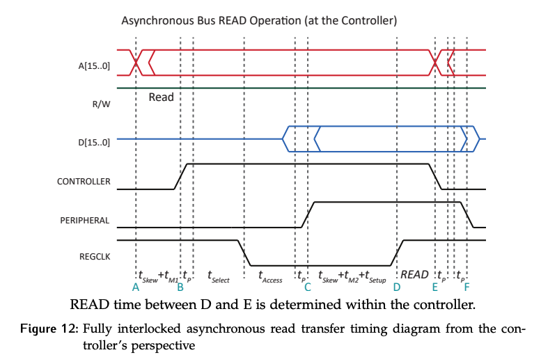
The regclk signal is generated inside the CPU for a read. This is the signal that will clock the data into the destination (in this case the MDR). Depending on the exact logic used, the falling edge could happen anytime between when the transaction starts and when the rising edge is needed to clock in the data. While not drawn that way here, a common approach is to use the assertion of controller AND R/W signal indicating a read to reset the signal. The rising edge must occur after data is stable and prior to controller being de-asserted.
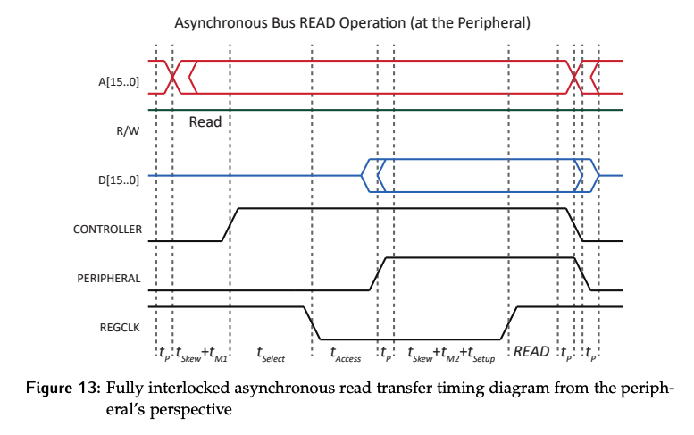
Timing Diagram - Peripheral Perspective
Here, the same transaction is shown from the peripheral’s perspective.
Write Transaction
Once again, the assumption is made that the controller and peripheral signals are de-asserted at the beginning of the transaction.
The transaction starts when the controller asserts the address and data values, and sets the R/W signal low to indicate a write. After and some margin, the controller signal will be asserted.
- Once again, controller does not have to be delayed by the propagation time, since the signal itself will still have to propagate to the peripheral.
- If the model wanted to be more conservative, additional time for the propagation of
address,data, andR/Wcould be allotted.
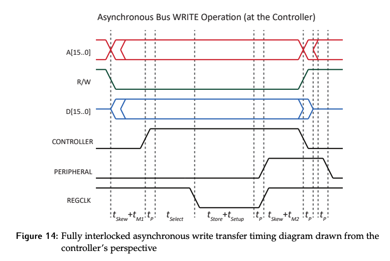
The assertion of controller is interpreted at the peripheral as “the address and control information are valid can be acted on”. Thus, and can take place, just as they would have during a synchronous transaction.
The regclk signal is generated at the peripheral since this is a write. The logic for this signal can no longer include the clock indicating the peripheral phase. Instead, it could be implemented as address decoded and and controller and !peripheral . Since the falling edge would be where want a rising edge, the whole signal can be inverted. Thus, we have:
- Using this logic,
regclkwill go low at the beginning of - A rising edge will be generated when
peripheralis asserted - In the diagram above,
regclkhas been drawn as it would be seen at the controller, so including a after it was actually asserted. In reality, this signal would never be seen by the controller, as there’s no need for it to be shared outside of the peripheral.
For a write, the peripheral signal will be asserted once the data has been stored. This is the peripheral telling the controller “I have finished my part of the transaction”.
Why is there after peripheral was asserted? Skew only applies to data and addresses (multi-line). This is a design decision, since it simplifies the hardware to use the same logic on the controller side regardless of whether the transaction was a read or write. Therefore, the controller waits after seeing the peripheral signal asserted before proceeding.
- After waiting this skew time and an extra margin time, the transaction will be cleaned up in the same way it was for a read: controller is de-asserted, and later it will see that
peripheralhas been de-asserted. The bus is now ready for the next transaction to begin.
The speed will be limited by skew time, which is largely a factor of the physical hardware used to drive the signals on the line. Same propagation time. Setup times and hold times may also need to be known to ensure correct operation.