The previous section explored the details of how the CPU-Memory interface transfers information between the internal CPU bus and the system bus. Let’s zoom out and take a look at the same transactions from memory’s perspective. It’s important to remember that while the other end of the transaction is being labeled memory, from the CPU’s perspective it doesn’t matter whether the CPU is talking to a physical location in memory or a peripheral device. It all looks the same to the system bus.
Recall the meaning of read and write in the context of the system bus in this course.
- A write transaction will transfer information from the CPU to memory (or a device register)
- Read will get information from memory (or a device register), and transfer it to the CPU. In other words, read and write are from the perspective of the transaction’s controller, in this case the CPU.
Consider a system with just a CPU and memory as shown in Figure 8. They are connected by a system bus with address lines, set by the MAR, control lines and data lines, which are connected to the MDR. The control signals are MARin, MDRin, MDRout, READ, WRITE, MFC.
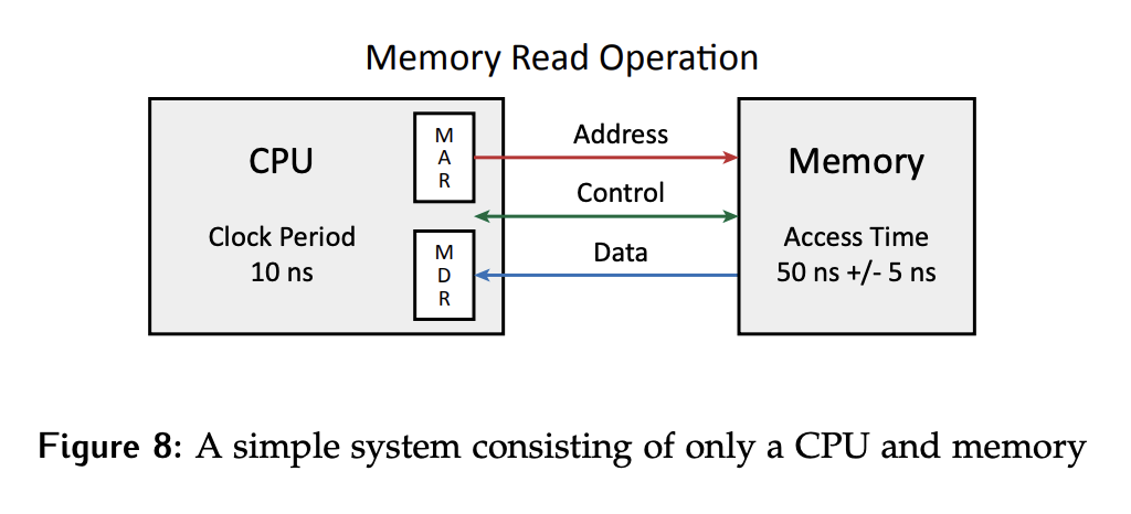
MARin,MDRinandMDRoutare all generated by the CPU and used to control information movement on the internal CPU bus.READandWRITEare also generated by the CPU, but they are used to indicate the direction of the system bus transaction.MFCis the only signal controlled by memory. Memory function complete will be asserted when the memory has completed the desired action to tell the CPU it is done.
Synchronization
The CPU runs on an internal clock with a 10 ns period while a memory access takes between 45 and 55 ns. How can information be transferred between these devices with vastly different views of time?
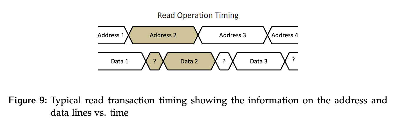
Regardless of the specific implementation details of the system bus, a read will always follow the same general pattern as shown in Figure 9.
- The CPU will place the address contained in the
MARonto the address lines of the bus. - There will then be some period of time where there is no valid data on the bus, as the CPU is not driving the data lines and the information to be read hasn’t been retrieved yet.
- It takes time between the address being set and the data being available. Based on the address, the target data will be retrieved and placed on the bus, at which point it is ready to be clocked into the
MDR.
There are two choices in how the system bus is clocked: synchronous or asynchronous.