Typical loads applied to a shaft:
Critical Locations
It is not necessary to evaluate the stresses in a shaft at every point; a few potentially critical locations will suffice.
Critical locations will usually be on the outer surface, at axial locations where:
- Bending moment is large
- Use shear force and bending moment diagrams to assess
- If forces are in two planes, we will need two sets of diagrams. Then, we can calculate the resultant moment.
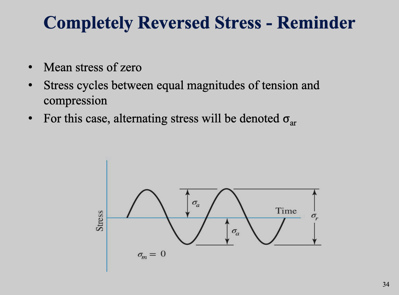
- Constant bending moment on a rotating shaft produces a completely reversed moment.
- Torque is present
- Typically enters shaft at one gear and leaves at another gear.
- Use FBD to assess.
- Stress concentrations exist
Axial loads are typically negligible compared to bending moment, torque, and stress concentrations.
Shaft Stresses
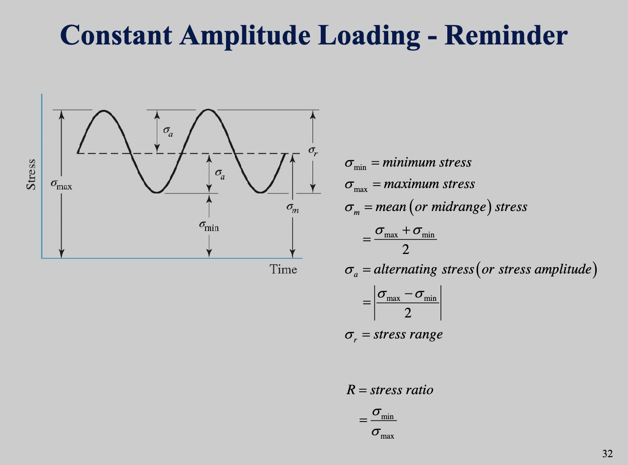
Bending, torsion, and axial stresses may be present in both mean and alternating components. If the shaft rotates, we have completely reversed stress; we need to determine mean stress and stress amplitude.
Bending, torsion, and axial stresses may be present in a combined loading scenario.
Stress Equations
Shaft-specific stress equations are presented here. Bending, torsion, and axial stresses may be present in both mean and alternating components. This is for dynamic loadings, where we account for the alternating stress (amplitude) and mean stress over a loading cycle.
The fluctuating stresses due to bending and torsion are given below. Axial loads are relatively very small at critical locations where bending and torsion dominate, so they will neglected.
- – shaft radius
- – shaft diameter
- – mean torque
- – second moment of area
- – mean bending moment
- – distance from centroidal axis
- – polar second moment of area
- – alternating/amplitude torque
- – alternating/amplitude bending moment
- and – fatigue stress-concentration factor
We can then use these values to derive von Mises stresses for rotating round shafts instead of static loads. Again assuming negligible axial loads, we have:
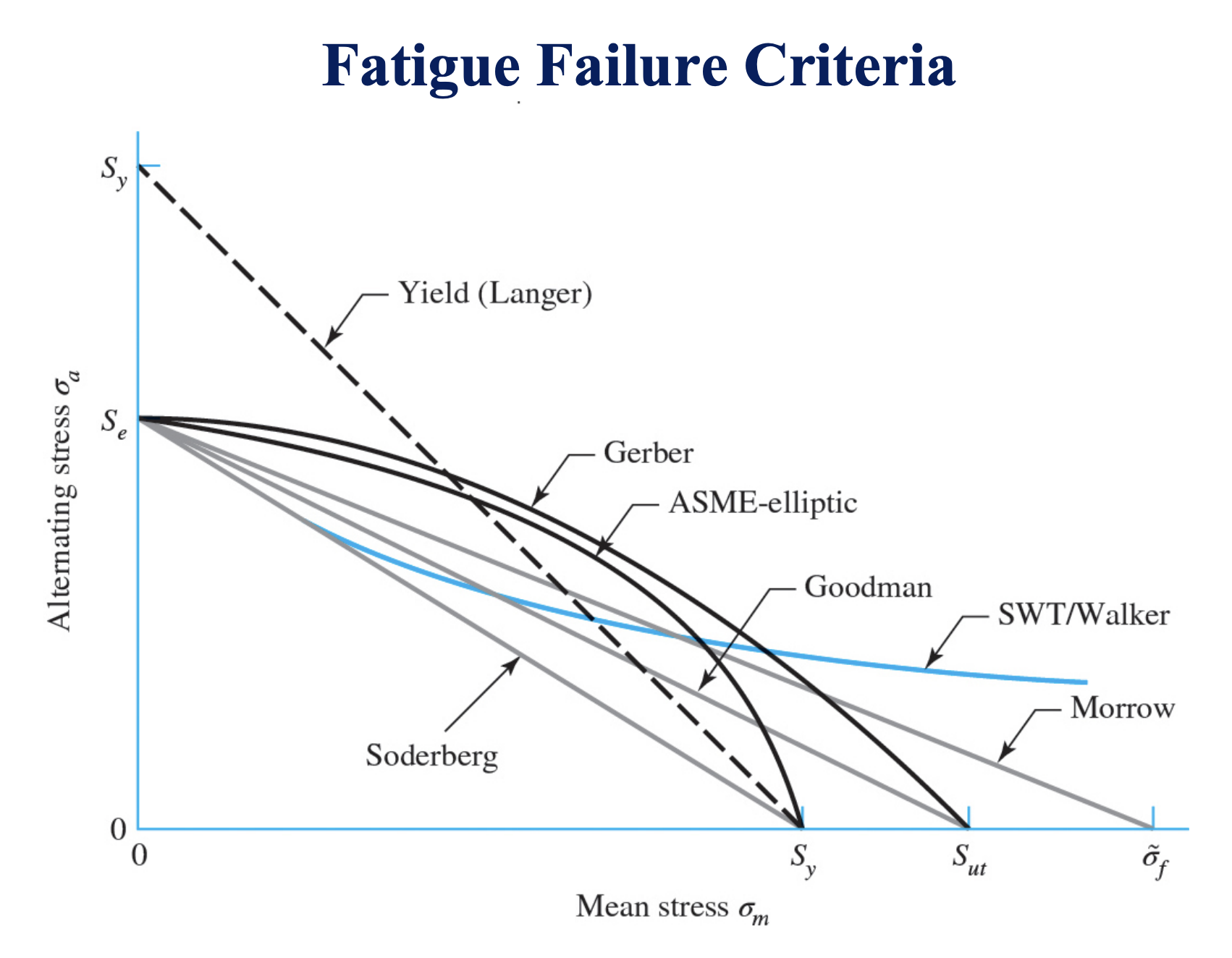
Shaft Fatigue Failure Criteria
The von Mises stresses above can be substituted into various failure criterion equations, which we can solve to find factor of safety , or diameter .
To keep the equations in simpler form, we first establish a pair of terms to be used in each of the criteria equations:
DE-Goodman:
DE-Morrow:
where:
- is factor of safety
- : Diameter of the shaft or component.
- and : Fatigue stress concentration factors for normal and shear stresses.
- : Alternating and mean moments.
- : Alternating and mean torques.
- : Endurance limit of the material.
- : Ultimate tensile strength of the material.
- : True fracture strength
- : Fatigue strength coefficient – used for deriving
- For steel,
DE-Gerber:
DE-SWT:
Shaft Yield Check
It is always necessary to consider the possibility of static failure in the first load cycle. A von Mises maximum stress is calculated for this purpose:
To check for yielding, we can then compare this to the yield strength as usual:
For a quick conservative check, we can use the estimate of .