Below we have the equivalent circuit diagram of a practical single-phase transformer.
- The magnetizing branch has been neglected for this analysis (can’t neglect if we’re calculating efficiency!).
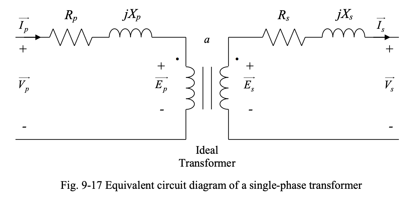
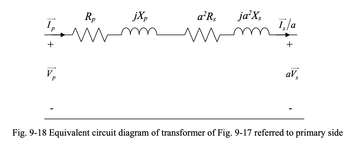
The equivalent circuit above can be simplified if the components on one side are transferred (or referred) to the other side. Below, the secondary circuit has been referred to the primary side.
Basic Referral Rules
When secondary current is referred to the primary side, it gets divided by the turns-ratio . This is based on the relation for current transformation:
When secondary voltage is referred to the primary side, it gets multiplied by the turns-ratio . This is based on the relation for voltage transformation:
When secondary impedance is referred to the primary side, it gets multiplied by the turns-ratio squared, . This is based on the relation:
The power and power factor do not change due to referral.
Further Simplification
We can combine the resistances and inductances above (9-18) to get an even more simplified circuit.
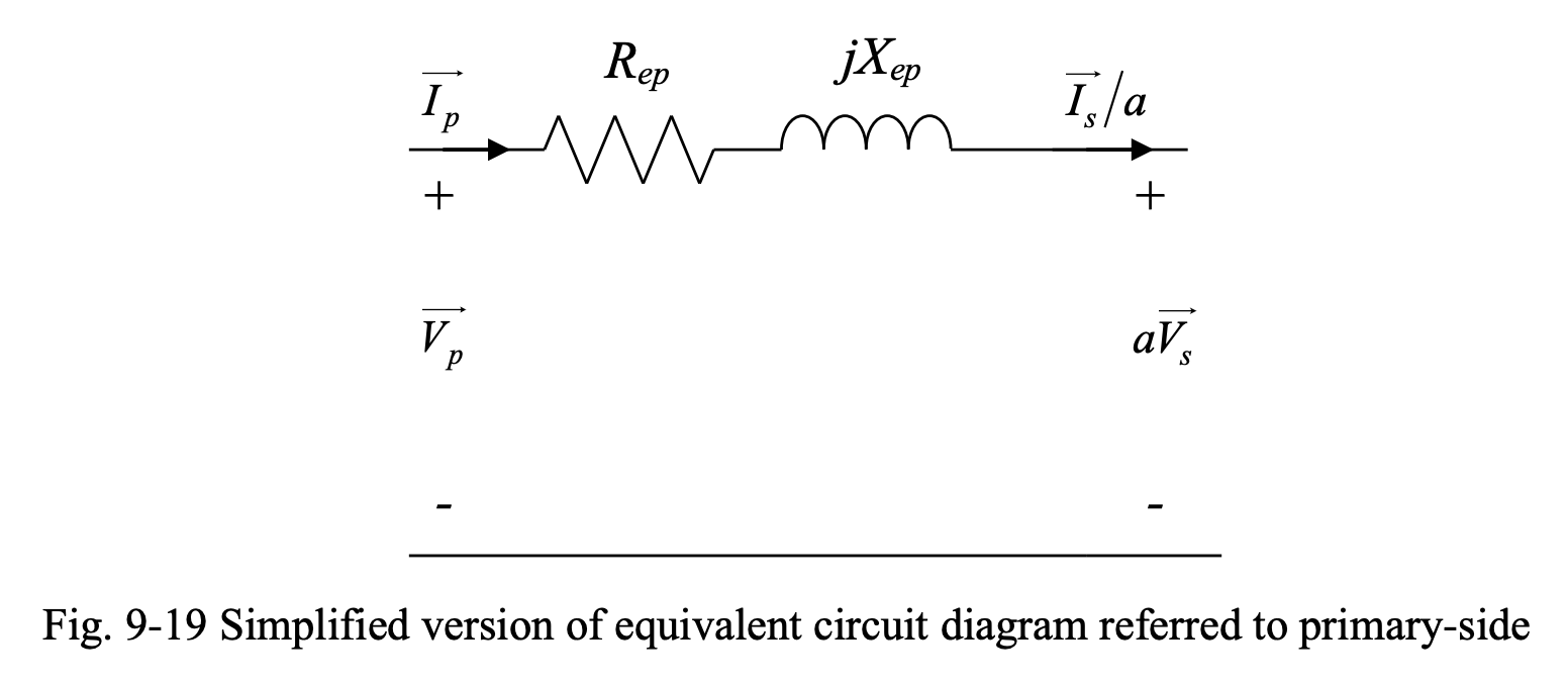
Here, we have:
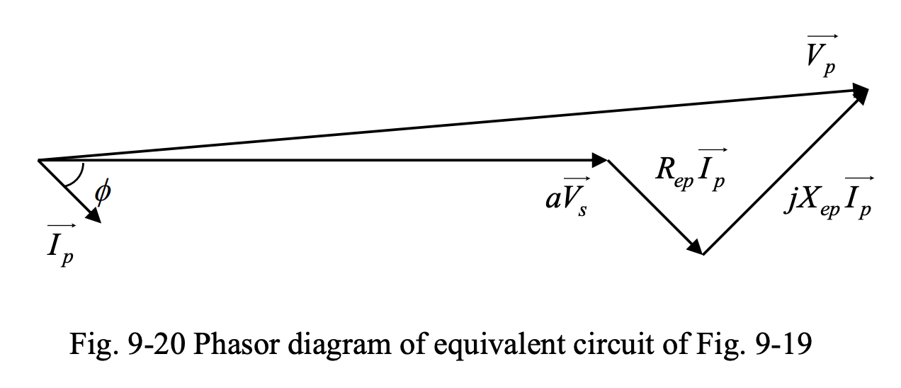
The phasor diagram of the corresponding circuit is given below.
Secondary Side Referral
If the primary circuit is referred to the secondary-side, and the resistances and inductances are integrated, we get the equivalent circuit shown in Fig. 9-21 and the phasor diagram shown in Fig. 9-22.
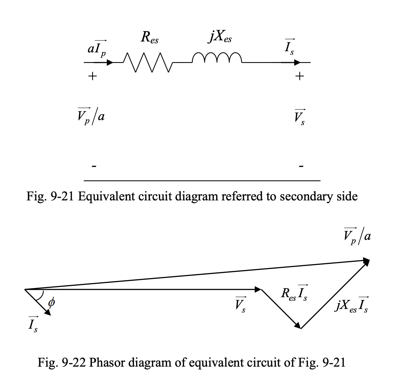
In this case: