The parameters of an Transformer Equivalent Circuit can be determined through two tests on the transformer.
Open-Circuit Test
The open-circuit test determines:
- – core loss resistance.
- – magnetizing reactance (reactance due to the magnetizing inductance of the transformer’s core).
In an open-circuit test:
- The terminals of the high-voltage (HV) side are open-circuited (no-load)
- Rated voltage is applied at the low-voltage (LV) terminals
- The power, voltage, and current are measured from the low-voltage side
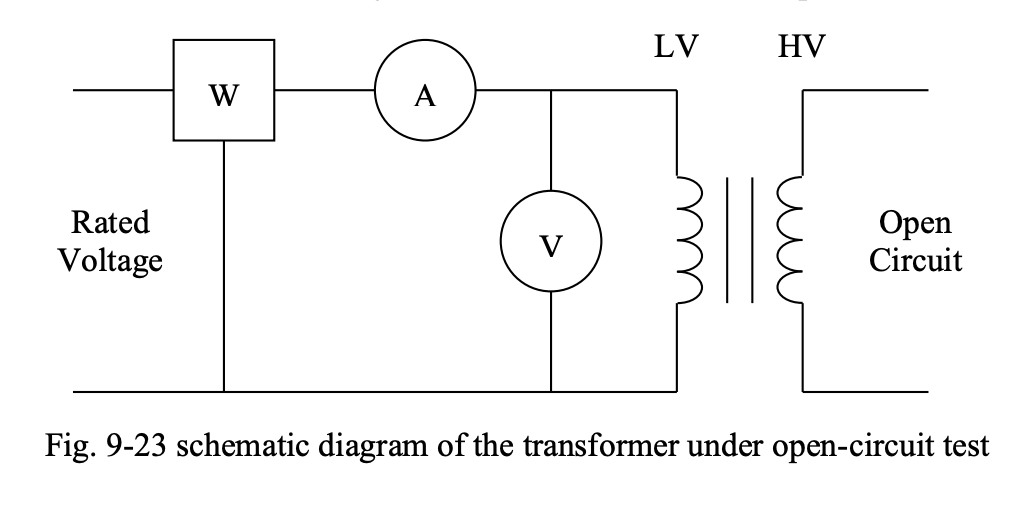
HV terminals are open-circuited and LV side is excited because it’s more convenient/likely to have a source that can produce the rated voltage on the low-voltage side. We’re also more likely to have a low-voltage wattmeter and voltmeter. The ammeter and the current coil of the wattmeter experience open circuit current, which is small, and thus, they are not matters of concern in this test.
Detailed circuit for open-circuit test:
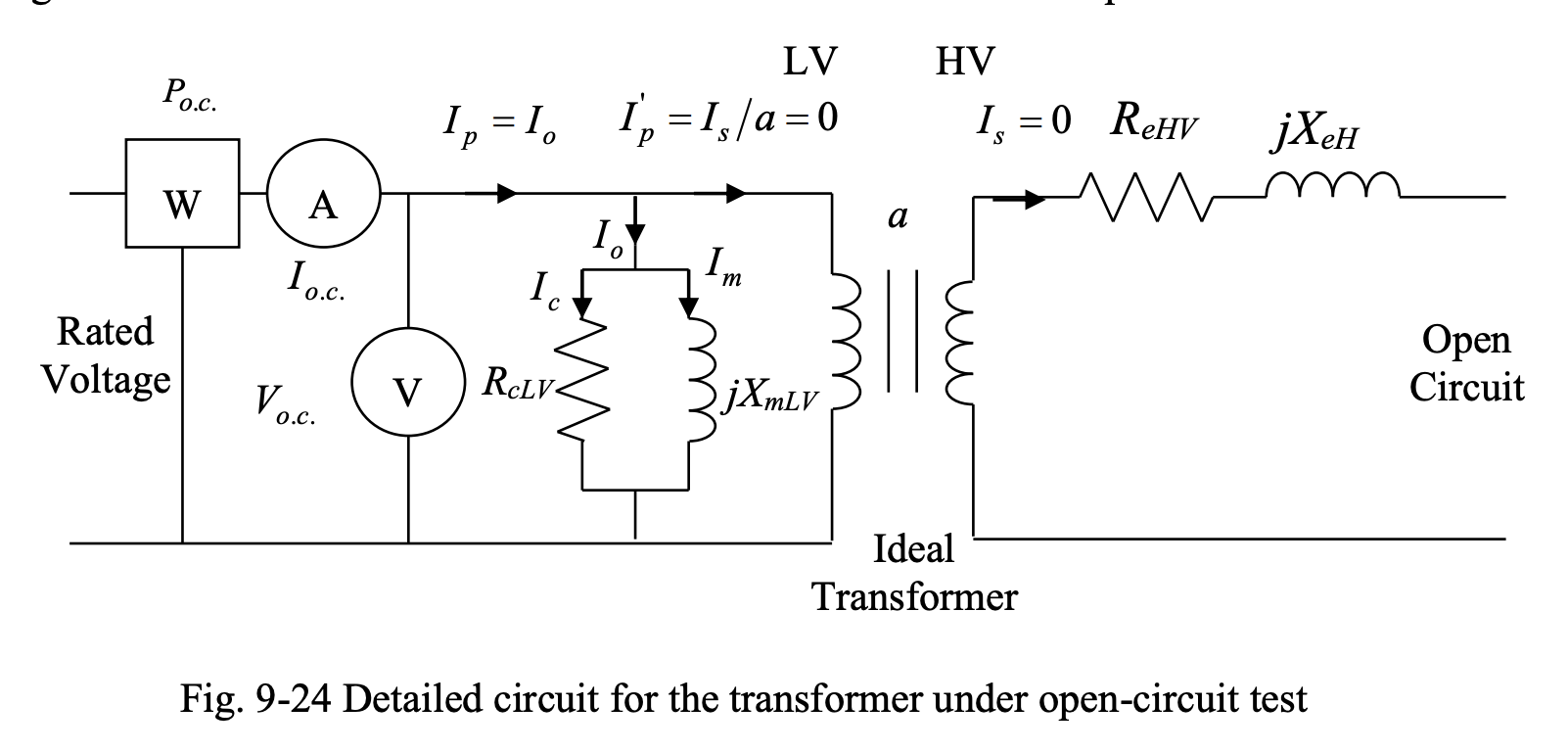
- The magnetizing branch is on the low-voltage side
- All resistances and inductances have been referred to the high-voltage side
- Since the secondary terminals are open-circuited, ; therefore, .
This can be translated into an open circuit on the primary (LV) side of the transformer:
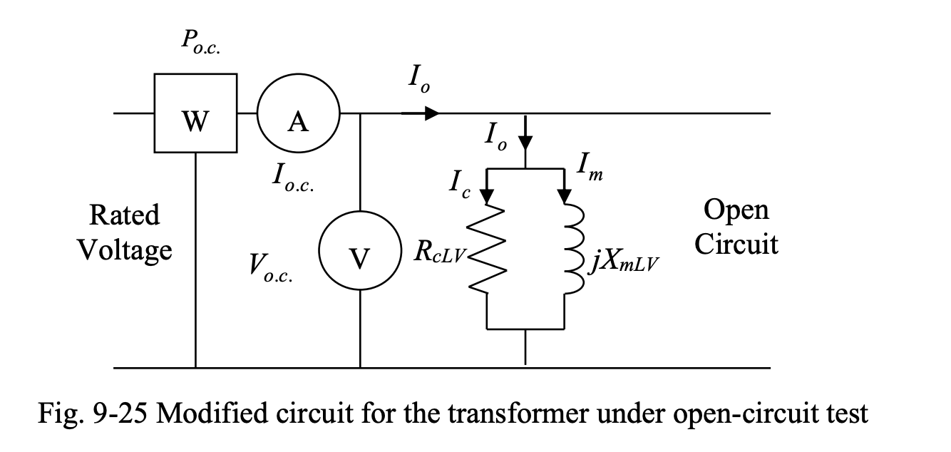
The power measured by the wattmeter in the open-circuit test is equal to the no-load loss of the transformer, as it only includes the core losses. From the above diagram, we can write:
and
and
Short-Circuit Test
The open-circuit test determines:
- – copper loss resistance
- – reactance due to windings (resistance and leakage reactance)
In the short-circuit test,
- The terminals of the low-voltage (LV) side of the transformer are short circuited.
- High voltage (HV) side is fed by a reduced voltage such that the short circuit current read from the ammeter is at most equal to the rated current on the high-voltage side.
- The power, voltage and current are measured on the high-voltage side.
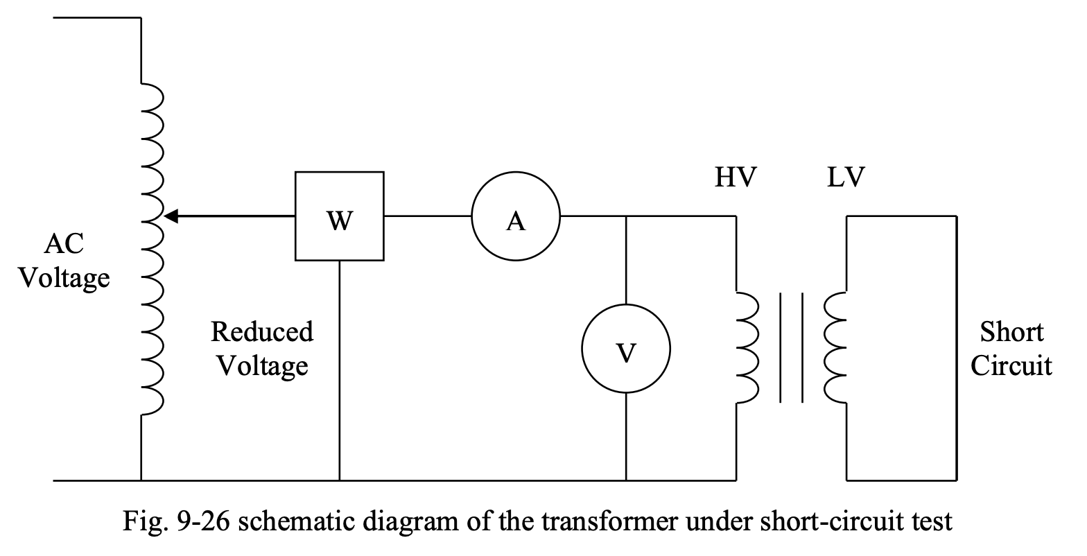
LV terminals are short-circuited and HV side is excited because it’s more convenient/likely to have a low-current wattmeter and voltmeter. Note that for the same power, high-voltage side has lower current than the low-voltage side. The voltmeter and voltage coil of wattmeter experience the reduced voltage, which is small, and thus, it is not a matter of concern in this test.
Below is the detailed equivalent circuit for this:
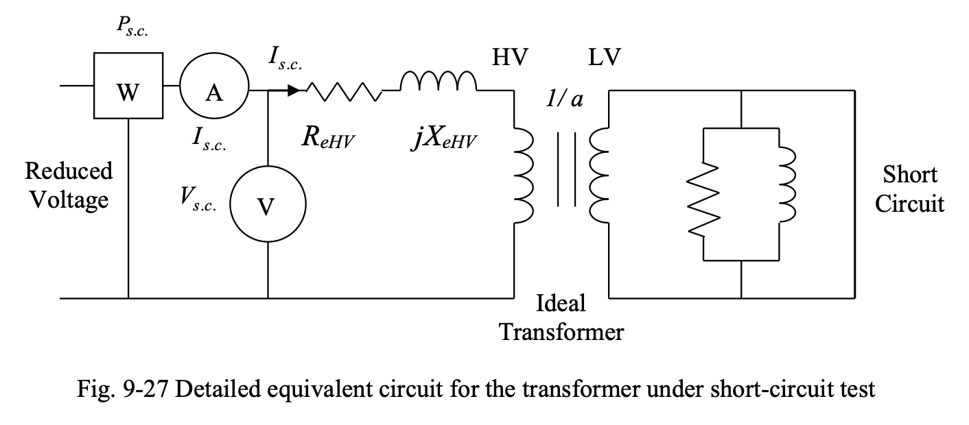
- The magnetizing branch is on the low-voltage side and all resistances and inductances have been referred to the high-voltage side.
- Since the low-voltage side terminals are short circuited, the low-voltage side terminal voltage will be zero.
This can be translated into a zero voltage on the high-voltage side and can be represented as a short circuit on the high-voltage side, as shown in Fig. 9-28:
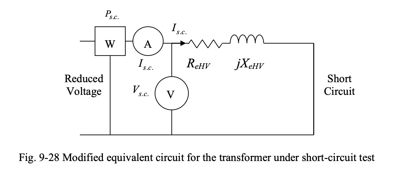
Note that the power measured by the wattmeter in short-circuit test is equal to the copper loss of the transformer, since it includes only the losses in the resistances of the primary and secondary sides. From Fig. 9-28, we can write:
and
and
Combination of Properties
We can combine all of the found parameters to find transformer equivalent circuit parameters.
The series impedance parameters and determined from the short-circuit test are directly equal to the equivalent primary-side parameters and :
We can also determine the equivalent shunt branch parameters based on and from the open-circuit test by referring them over to the primary side:
where:
Most notably, we can use:
Remember that in the tests, and are referred to the high-voltage side and and are referred to the low-voltage side. To refer to a different side, the values found must be multiplied by the appropriate factors.