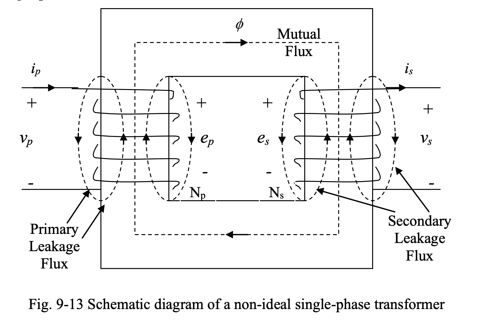
Unlike an ideal transformer, in a real transformer, there various things we can’t ignore:
- Primary and secondary windings have resistances and inductances
- Core experiences eddy current and hysteresis losses
- Permeability of the core material is finite, resulting in non-zero reluctance
- Leakage fluxes exist on both primary and secondary sides

There are two components of flux on each side of the transformer.
- Leakage flux exists only around the primary and secondary winding.
- Mutual flux is common to primary and secondary windings.
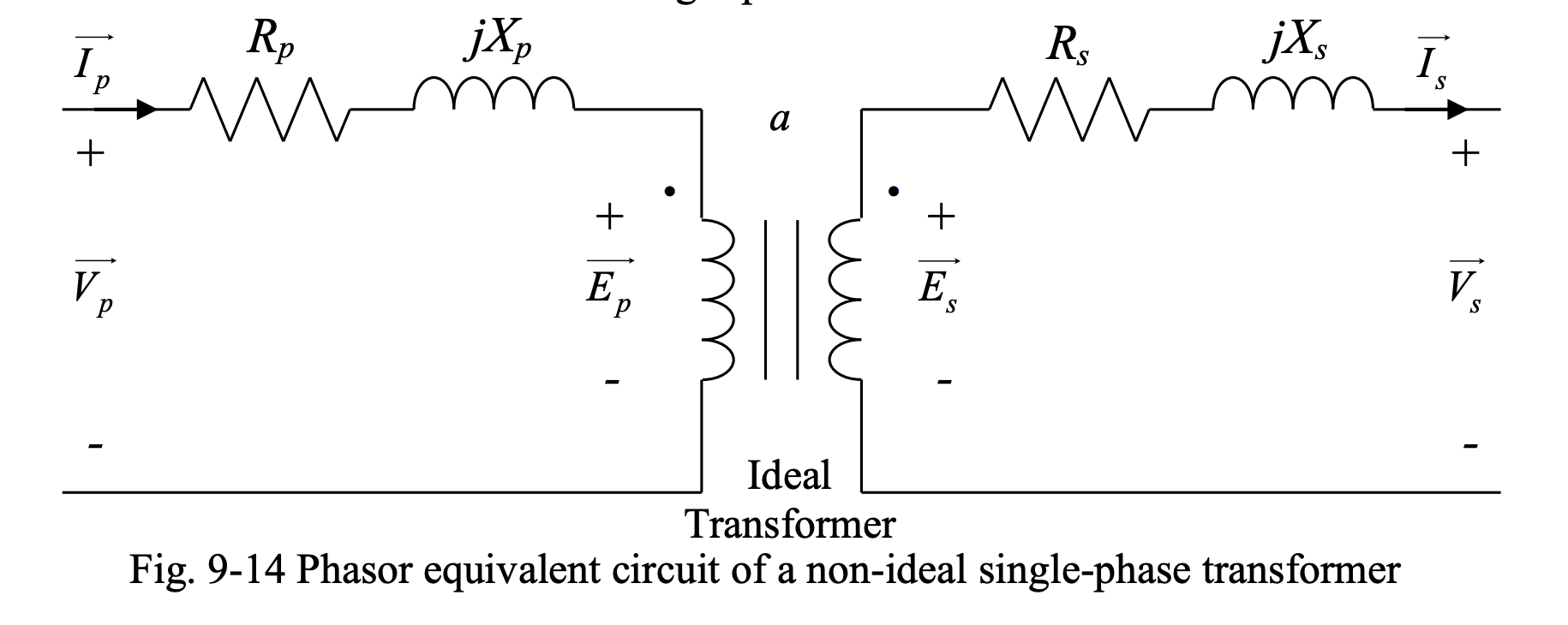
Mutual flux induces voltages and on the primary and secondary sides. The leakage fluxes on both sides also induce voltages on the primary and secondary sides. These voltages behave as inductive voltage drops in the primary and secondary circuits and are modeled as leakage reactances in series with the primary and secondary circuits. The windings on both sides also have resistances that are in series with the primary and secondary circuits.
Phasor Equivalent Circuit
Based on the above, we can create a phasor equivalent circuit:

The voltages, currents, resistances and inductances (or leakage reactances) of the primary and secondary sides can be related as:
and
Core Losses
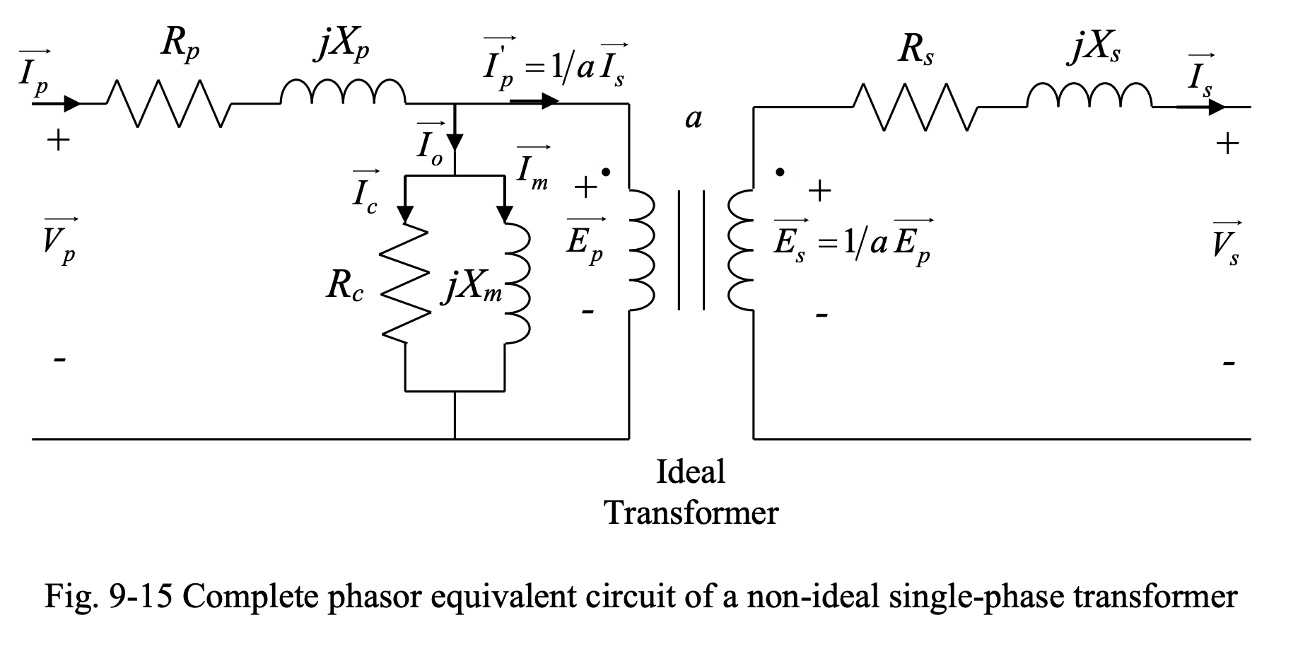
We also need to account for the core losses. In order to include the effect of core losses, a shunt branch is added to the primary side of the transformer. This shunt branch is composed of:
- A reactance . We use the fact that core losses are proportional to the square of the primary-side voltage to model the core loss by a resistance connected across , such that:
- Magnetizing reactance . This represents the path for the current that magnetizes the core.
The resistance and magnetizing reactance are usually very large compared to those of resistances and leakage reactances of the primary and secondary windings.

When the transformer is not loaded, . Thus, we have . However, . This current is the total current of the shunt branch, and is called the no-load current; it’s the current drawn by the transformer from the supply at no-load. This current is divided into two components:
- represents core losses, or no-load losses.
- represents the magnetizing current.
- Note that is usually very small and the losses in at no load can be neglected. It is due to the no-load losses that the transformer gets warm even when it is not loaded.
- Under load, copper losses, which are the losses due to the resistances of primary and secondary circuits, are added to the core losses (no-load losses) to make the total loss in the transformer.
Since the impedances of the shunt branch is normally very high (especially in large power transformers), the current is negligible compared to the currents in the windings. As a result, the shunt branch is usually neglected in the analysis of transformers. If the efficiency of the transformer is to be calculated, the shunt branch cannot be neglected, as it contains the resistance standing for the no-load or core losses.