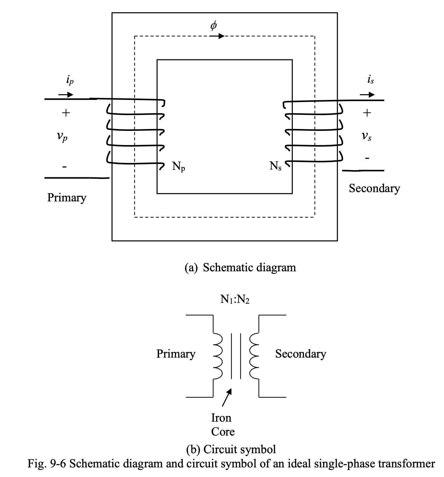
In an ideal transformer, there is no copper loss and core loss. The core has infinite permeability, and thus there is zero reluctance.

From the fact that the sum of mmfs around a magnetic circuit is equal to zero, we have:
where the subscript indicates primary and is secondary.
This can be re-arranged to:
Since the ideal transformer is lossless, its instantaneous power input will be equal to its power output:
which can be re-arranged as:
This can be combined with the previous relation between and to get:
Here, is called the turns ratio of the transformer, and is the ratio of the number of turns of primary winding to that of secondary winding.
Principle of Operation
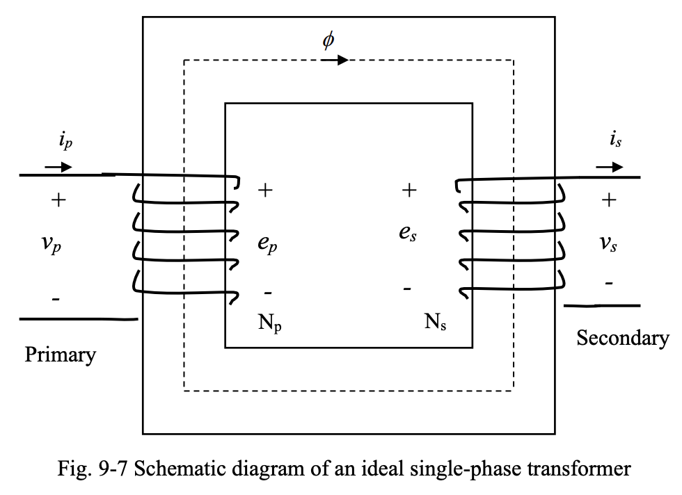
Below we have an ideal single-phase transformer.

Assume that a sinusoidal voltage has been applied to the primary terminals. A sinusoidal current will result and a sinusoidal magnetic flux will be setup in the core. According to Faraday’s Law, voltages and will be induced in the primary and secondary windings; since these windings are ideal, with no winding resistances and inductances, so and .
Thus, the voltages and can be expressed as:
The peak values of the voltages induced in the primary and secondary windings can be found as:
and the RMS values are:
Dividing by by , we get:
Note that since the resistances and inductances in the primary and secondary circuits have been neglected, and . As a result, the main relation for voltage and current transformation becomes:
Based on the value of the turns-ratio , the equation above presents the voltage and current transformation relations for 3 different types of transformers:
- Step-Down Transformer:
- Step-Up Transformer:
- Isolation Transformer: