Open-Drain Buffer
If the transistors between the supply voltage and the output in a push-pull driver were removed, all that would be left is the transistor between the output and ground, and the inverter driving its gate.
- When the input is a 0, the gate will see a logic 1 and the transistor will be on, or acting like a short circuit and actively pulling the output to ground.
- When the input is a 1, the gate will see a logic 0 and the transistor will be off, or acting like an open circuit. Thus, the output does not have any voltage, high or low. There’s nothing else in the circuit to drive the output. This means it is floating, or high impedance/high-z.
When built with an NMOS, this is called an open-drain buffer.
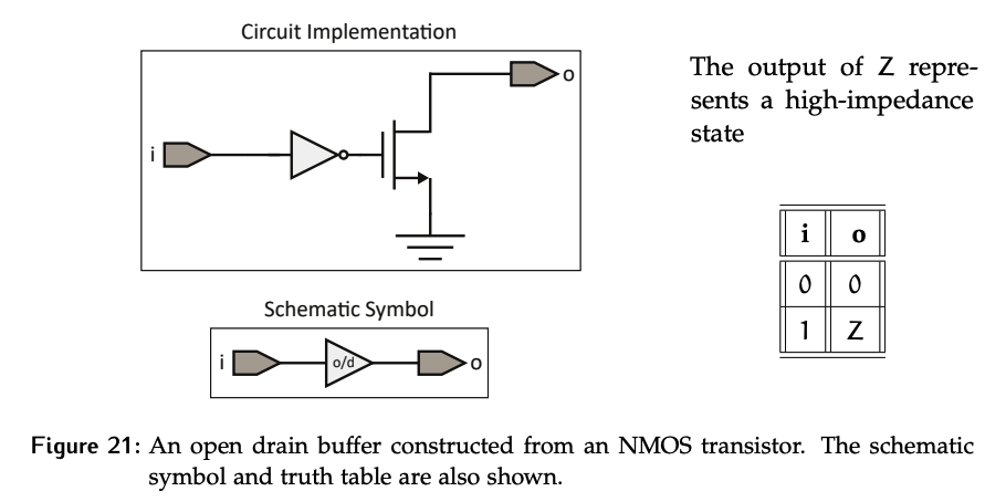
The open-drain buffer is part of the open-drain logic family. Any of the standard gates can be implemented using open-drain logic. For a given transistor configuration, its open-drain counterpart’s truth table just has Z’s instead of 1’s.
Open-Source Buffer
Similarly, if we remove the bottom NMOS transistor from a push-pull driver, we’ll have just a PMOS between the supply and output, which implements an open-source buffer. The same extension can be made to remove the NMOS transistors from all gates, creating the open-source logic family.
Multi-Device Conflict
An open-drain buffer can only actively pull the line to a low state. Multiple devices can be connected to the same line because when a device’s output is not active, it is in a high-impedance (Hi-Z) state. If multiple devices try to pull the line low simultaneously, there is no conflict because they are all pulling to the same state.
Pull-up Resistors
However, we don’t want floating lines; everything in digital logic should be a 1 or 0. Thus, we can add a pull-up resistor that is connected between the supply voltage and the output.
- While often used together, pull-up resistors are not part of the open-drain driver! Only one pull-up resistor can be in the circuit no matter how many open-drain drivers share a line; otherwise, the resistors would be in parallel and reduce the equivalent resistance each time another driver is added.
- Using an open-source buffer means we use a pull-down resistor instead.
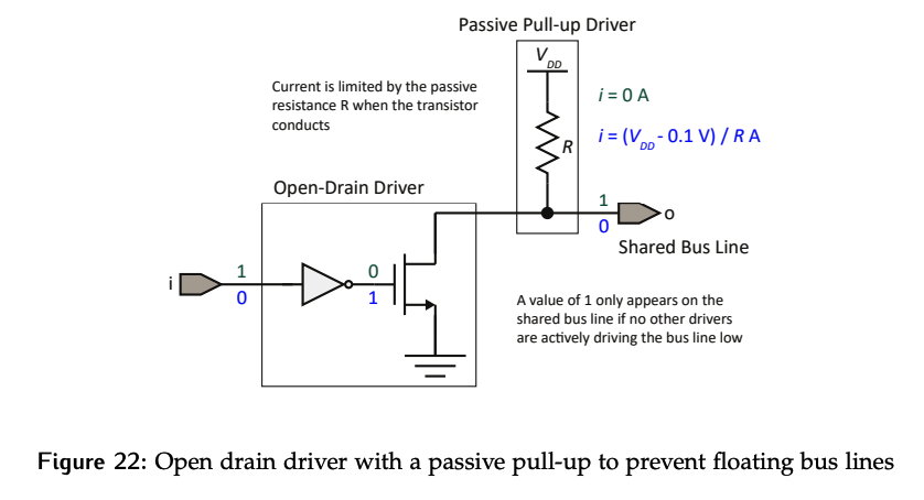
Resistors implement passive logic; they can be combined with active elements, but will never create a short circuit.
- When the transistor is off, there will be essentially no current through the resistor as the voltage drop across it will be almost 0 V.
- When the transistor is on, there is a path from the voltage supply through the resistor, then through the resistor to ground. There will be a voltage drop of minus the drop across the transistor across this resistor. These resistors are typically quite large, so the current through it wills tay small.
Conflict Free Driver Implementation
Combining two open-drain drivers with a pull-up resistor results in the practical and conflict free driver implementation shown in Figure 23.
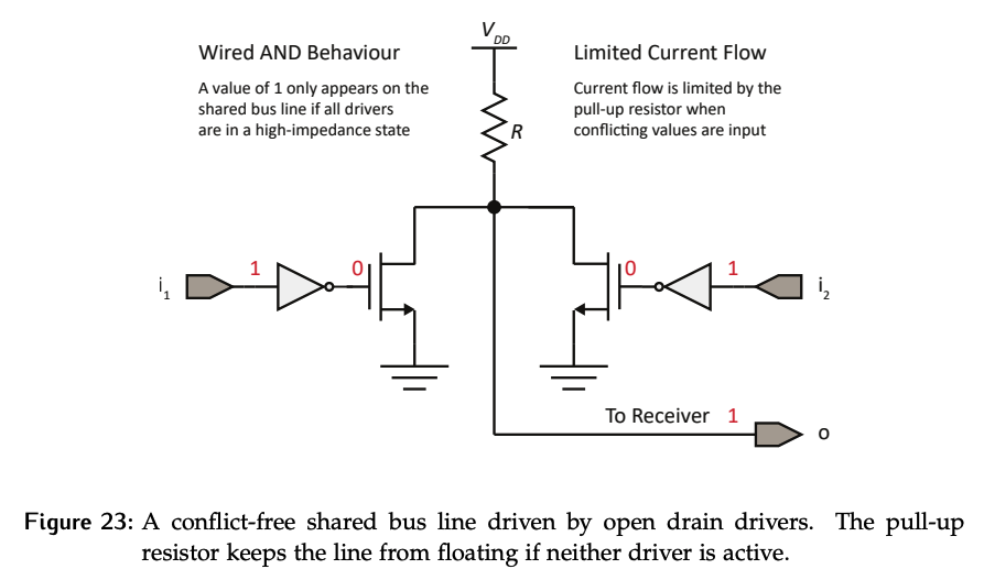
- If both inputs are a 1, both transistors are off and the pull-up resistor will passively pull the output to a logic 1.
- If one of the inputs is a 0, that transistor will be on and actively pull the output to 0. The other driver will still have a high impedance output and the pull-up resistor is still driving a passive 1.
While it might initially seem like there is a conflict, there isn’t. An active 0, meaning it’s driven through a transistor, will beat a passive 1, meaning it’s driven through a resistor, without creating a conflict. Recall the hierarchy: active, passive, high impedance.