The Inter-Integrated Circuit () protocol was designed for short-distance communication between multiple chips within a single device. It’s designed for shorter distances, so it’s typically found between chips on the same PCB or chips on separate PCBs that connect to one another. For example, some shields on Nucleo boards use I2C to communicate between the microcontroller and devices on shields.
I2C was originally developed around 1982 for internal use to facilitate communication between their chips. The first version allowed for 100 kHz data speeds and used 7-bit addressing. In 1992 a public version of the specification was released that added a second speed, 400 kHz, and expanded the address space to 10 bits. The 400 kHz speed is faster than UART but slower than the SPI protocol that will be considered next.
Hardware and Principles
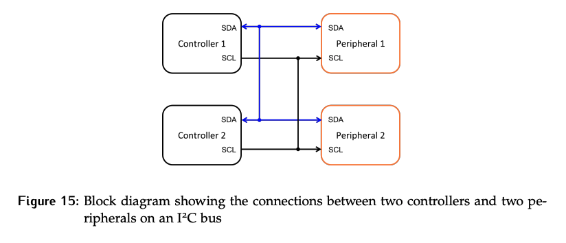
I2C uses only two wires: one for clock (SCL) and one for data (SDA).
- Since only one data line is used, the protocol implements half-duplex communication.
- Unlike UART, multiple controllers and multiple peripherals can share the same lines. Thus, addressing is now required to determine which peripheral is the target of the transaction.
- There is a mechanism for controllers to get con to get control of the line, and once in control, the controller can communicate with any peripheral. Controllers cannot communicate with each other.
Data Synchronization
For MTE 325, how data synchronization is achieved is of particular interest.
Bit rate synchronization and bit phase synchronization are achieved using the shared clock.
- The controller sets the data value when
SCLis low, and the peripheral samples bits on the rising edges ofSCL. - The clock is only toggled while sending information – it is not free running.
- The use of a shared clock has removed the need for start and stop bits on each byte, which in turn reduces the overhead.
- The shared clock has also removed the issues identified with UART related to differences in clock rate and phase between the two sides.
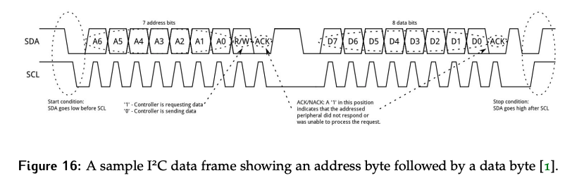
Byte synchronization is achieved using a special pattern called the start condition on the lines to mark the start of a frame. Specifically, the SDA line is pulled low, while the SCL line is still high.
- This works because the idle state of the lines is high, and during a transmission, the data must change while clock is low. Therefore, this unique pattern can be used to signify the start of a frame, and by extension the start of a byte.
- Once the controller has set the start condition, it will begin toggling the clock and shifting out the address, starting with the MSB.
- The address bits are followed by a
R/Wcontrol bit used to indicate if a read or write transaction is taking place. - This is followed by an
ACKor acknowledgement bit, which ensures that the peripheral is present and responding. - While the controller was responsible for driving the clock and sending the address bits, it is the peripheral’s responsibility to pull
SDAlow after theR/Wis received to indicate it has seen its address and is participating in the transaction.
There will then be at least a 1-bit period where the SDA line idles before the first data byte is sent.
- If the transaction is a read, the peripheral will drive the data on
SDAone bit at a time, starting from the MSB. The shifting out of the data bits is still controlled with the clock driven by the controller. - If the transaction is a write, the controller drives both the
SDAandSCLlines. The data byte is also followed by anACKbit, and whichever device is receiving the data is responsible for transmitting a 0 during this time period. - The number of bytes to be sent or received must be known by the controller in advance, as it is responsible for driving the clock for the correct number of cycles. Typically, this information can be found in the peripheral’s data sheet.
Once all data bytes in a frame are complete, the controller is responsible for marking the end of the frame with a stop condition. The stop condition is a rising edge on SDA while the clock is high. The combination of start and stop conditions achieve block synchronization for I2C.
Since I2C supports multiple controllers, there must be a mechanism to prevent conflicts on the lines. In this case it is achieved through the use of open-drain drivers.
- Recall that open-drain drivers are able to assert a logic 0 through a transistor but a separate pull-up resistor is required to assert a 1.
- The inability of any device in the system to actively drive a 1 ensures there can never be a conflict on the line and therefore devices will not be damaged in the event that multiple devices attempted to drive the lines at the same time.
Strengths and Weaknesses
Advantage of I2C:
- Dedicated clock line removes need for known and accurate clocks at each device.
- No start/stop bit overhead.
- Devices are protected with open-drain drivers.
Disadvantages of I2C:
ACKbit overhead- Limited to slower speeds than SPI
- Half-duplex communication