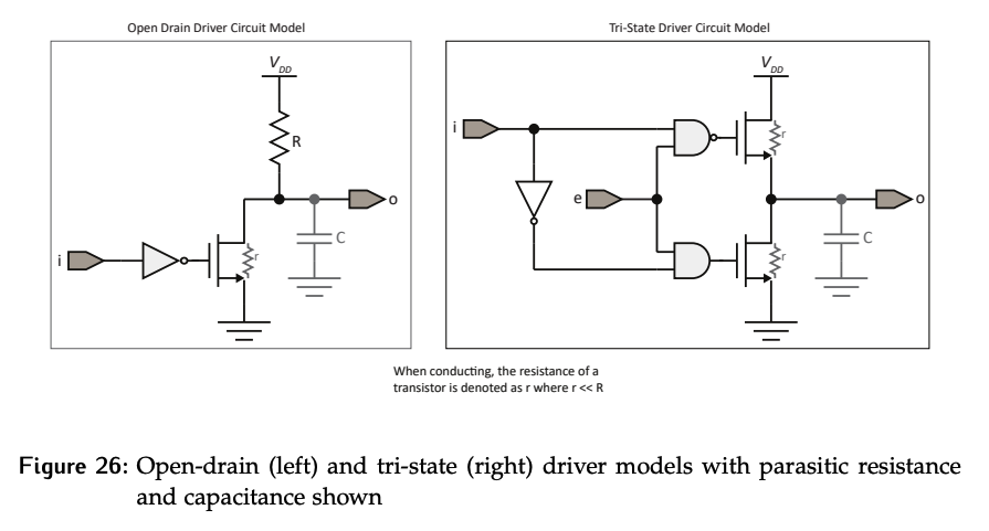
So far, parasitic resistances and capacitances have been ignored. In order to discuss the trade-offs between using the permanent fix of open-drain driver and the temporary fix of tri-state driver, we will consider their effects.
When a transistor is on, it will not behave as a perfect short. It will have a small parasitic resistance, . The output line is also imperfect; it will have an associated capacitance, .
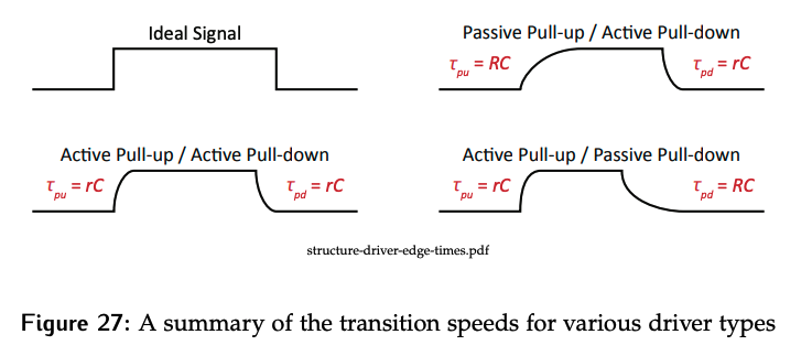
Transition Times
An ideal signal would change instantly, but if the non-ideal nature is taken into account, there are RC transients present. This means the speed at which the signal transitions is dictated by the time constant, .
Open-drain driver
For an open-drain driver in combination with a pull-up resistor (top right - Passive Pull-up/Active Pull-down), the parasitic resistance of the transistor will be much smaller than the resistance of the pull-up.
- When the output transitions from 0 to 1, current will flow through the pull-up resistor, giving the transition time .
- When the output transitions from 1 to 0, the current will flow to ground through the transistor, resulting in a time constant .
Because , it’s much faster pull the output value down to 0 and it is to pull it up to 1. Choosing a precise value is important; a small means a large and slow transistor is needed to handle the current, and a big results in slow changes.
Tri-State Driver
For a tri-state, both paths are through transistors, so they will have the same time constant and both will be relatively fast.
Comparison / Trade-offs
The slow pull-up time on open-drain is one of the major trade-offs. While they require less hardware, the different transition times make them unsuitable for multi-bit bus lines. Depending on the transition a bit is undergoing, the transition times would have different characteristics.
The simpler hardware of open-drain devices and eliminating the need to generate exclusive enables is still useful. The most common application is shared interrupt lines, where open-drain logic allows multiple devices to share the line safely. An example is interrupt configurations.
Worst Case Scenario
Consider the worst case scenario for each of the driver configurations in Table 1.
- The pull-up column describes the path between the supply voltage and the output.
- The pull-down describes the path between the output and ground.
- The path can be through a transistor (active) or resistor (passive) depending on the type of driver being considred.
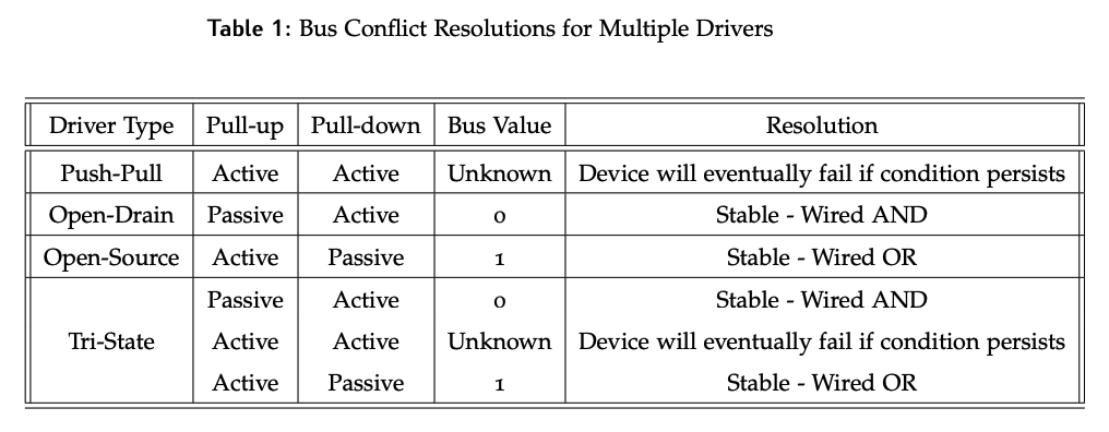
In the push-pull case that both these paths are active and as a result a short can be created that damages the device. With open-drain or open-source, one side can be active while the other is passive, so there will never be a damaging state.
The behavior of open-drained drivers is sometimes referred to as a wired-AND, as the logic with multiple drivers will result in the AND truth table: the output is only 1 if all the inputs are 1. Similarly, an open-source driver is referred to as wired-OR.
In the tri-state case, the only way to have both paths active is if the enables are not exclusive, which would just be the same as the push-pull and result in damage. A properly implemented tri-state system should never get here.