Serial Peripheral Interface (SPI) is a common synchronous protocol for serial systems.
- Similar to I2C, it is used for chip-to-chip communication on the same PCB, or between PCBs that connect to one another. It is not typically used in applications where a cable would be required to connect the chips.
- One of the reasons SPI is very popular is that it requires trivial hardware – it can be implemented using only shift registers.
- SPI does not support multiple controllers on the same set of lines, but there can be multiple peripherals.
The SPI protocol uses separate lines to send and receive data. There are two different naming conventions for the data lines at present, depending on device capabilities.
- For devices that can act either as a controller or peripheral, we use peripheral in controller out (
PICO) and peripheral out controller in (POCI). - For devices with fixed roles, serial data in (
SDI) and serial data out (SDO) may be used instead.
In addition to data lines, SPI uses a discrete clock line, SCK. Whether data is sampled on the rising or falling edge is device-dependent. There is no speed specified by the protocol but 20-66 MHz is typical.
Addressing can be done in several ways.
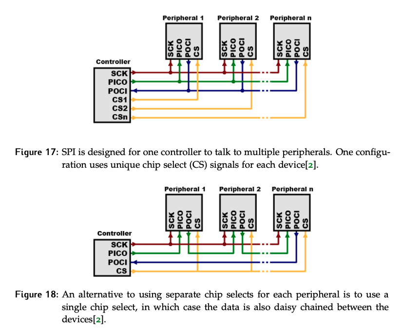
- The first way is to use separate chip select (
CS) signals for each device in the system as shown in Figure 17. Only oneCSsignal is asserted at a time, so there is no need to assign addresses or send them over the data lines. If the peripheral’sCSline is asserted, it is the one involved in the transaction. - The second way is to use a single
CSline with daisy-chained data lines. This is typically used in output-only situations.- Note that the first data sent will end at the last peripheral; the controller must ensure that the clock is toggled the correct number of times for the data to shift all the way to the last peripheral. This in turn means the controller must know how many peripherals are in the chain.
Sample Transaction
A sample transaction on the SPI bus is illustrated below.
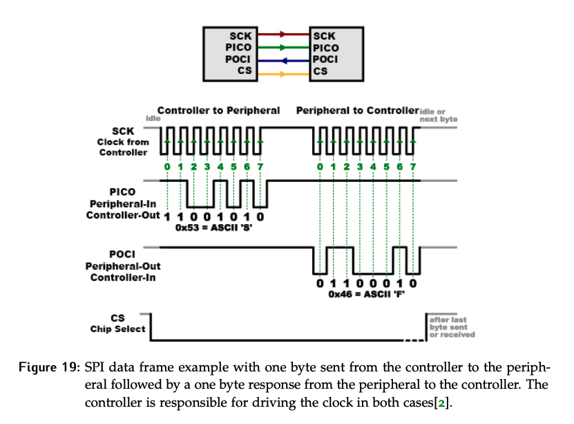
The controller is always responsible for generating the clock signal, so any transaction will always start with the controller. The controller asserts CS, then sends at least 1 byte to the peripheral. This byte is typically a command telling the peripheral what to do (e.g. return a sensor reading).
- If the transaction is a write, subsequent bytes sent to the peripheral will contain the data to be written.
- If the transaction is a read, the device responds with the data.
The data size must be known in advance so that the controller knows how many bytes to clock. This is not really a problem, as SPI is heavily used in situations with well-defined command structures. While the data illustrated in this diagram is translated to ASCII text characters, it is more common that raw binary is being sent between the controller and the peripherals.
Strengths and Weaknesses
Advantages of SPI:
- Supports higher transfer speeds
- Implemented with simple hardware (shift registers)
Disadvantages of SPI:
- Requires multiple
CSlines or additional shifting of data bits - Requires more pins
- Communication format has to be well-defined in advance.