Two systems that need to exchange information need to agree on a common language, called the communication protocol. In any communication system, a protocol or a combination of protocols is typically used to address:
- Timing
- Control
- Format
- Data representation
- Electrical signaling (signal voltages, currents, connector pin-outs, etc.)
Frame Structure
The first protocol to be considered is a common asynchronous protocol called the universal asynchronous receiver transmitter (UART).
- Commonly used to communicate between devices such as microcontrollers and terminals on a computer.
- Only supports communication between two devices, so no addressing is required.
In the context of serial interfaces, “asynchronous” means each side has its own clock. These serial ports are shown below, with each side using its own local oscillator to drive both its transmit and receive clocks.
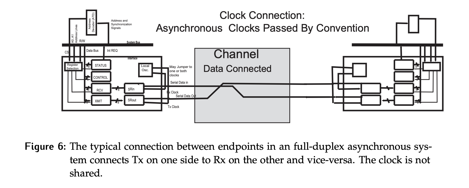
- Both sides must agree on a nominal clock rate, so that the deviation between the clocks is within a certain tolerance.
- Typical rates include 600, 1200, 2400, 4800, 9600, 19200, and 115200 bits per second (bps).
- While the rate can be determined by agreement, it will be shown shortly that the phase information must be communicated with the frame being transmitted.
- In terms of the channel, only the data lines have been drawn. In reality there would be a ground wire shared between the two sides as well to give a reference for the signal voltages.
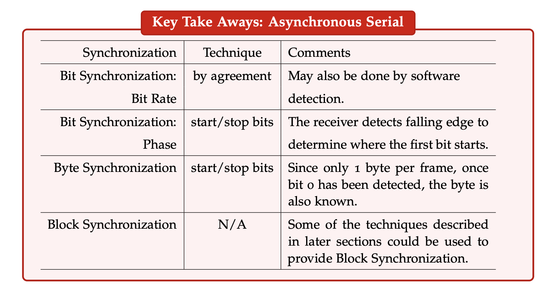
Bit Rate Synchronization
In Figure 7, a typical asynchronous data frame is shown, transferring one byte of data. The structure is designed assuming:
- The receiver has reasonable estimate of where the bit should start (phase synchronization).
- A nominal frequency has been agreed upon.
Fulfilling the above achieves bit rate synchronization. The goal is to sample the bit in the middle. This minimizes the error that can compound between the sampling of the first bit and the last bit in the frame, without erroneously double sampling a bit or missing a bit entirely.
Structure
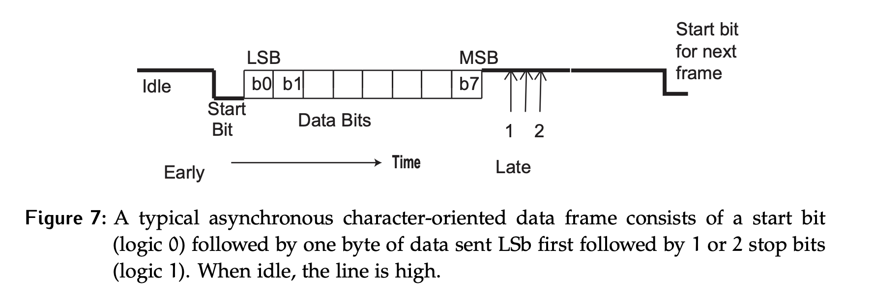
The frame consists of 10 or 11 bits in this order:
- 1 start bit, a logic 0
- 8 data bits (or 7 data bits + 1 parity bit), sent LSb, to MSb
- 1 or 2 stop bits, a logic 1
If the line is idle, it goes to a logic 1. This, in combination with the stop bits being a logic 1, ensures that there is always a falling edge preceding the logic 0 of the start bit.
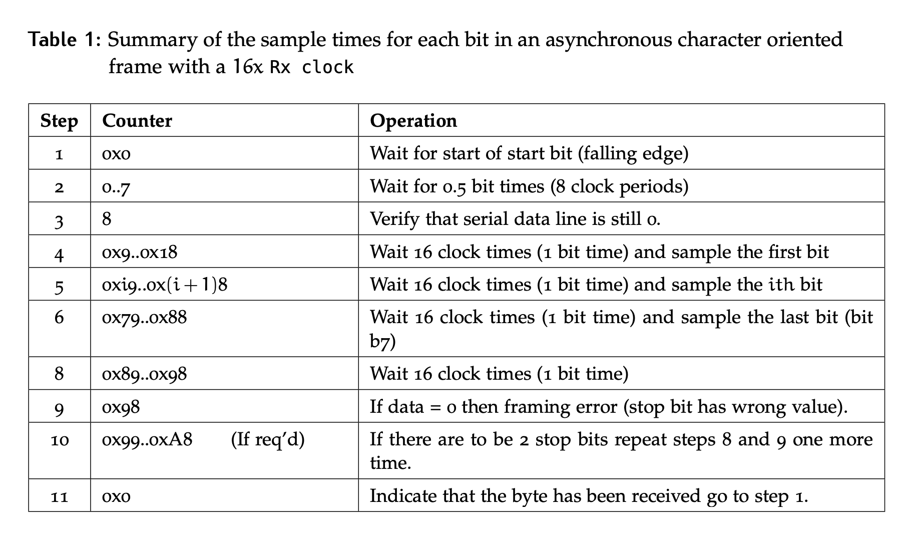
Bit Phase Synchronization
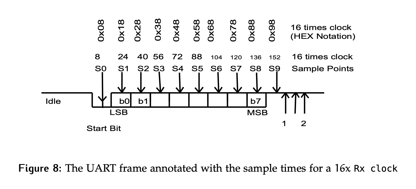
Bit phase synchronization is achieved through the use of the start bit. The falling edge that corresponds to it is used to reset a counter on the receive side. Since the receive clock is typically a multiple of the transmit clock (see clock phase alignment), sampling is done at the appropriate counts to use the edge as close as possible to the middle of the bit.
The counts are based on the goal of sampling in the middle of each bit. For example, the table and figure below shows an Rx Clock that runs at the Tx Clock frequency.
Byte Synchronization
In this operation, byte synchronization is inherent. Since the length of a bit and the format of the frame is agreed upon, the receiver can correctly identify the start and stop bits, thereby extracting the byte of data (8 data bits in the frame) accurately.
- In the case of 1 stop bit, it is tested by considering the line’s value at clock 0x98
- If there were 2 stop bits, there would be an additional test at 0xA8.
Overhead
Overhead is defined as:
For UART:
- Worst case – 1 start bit, 1 parity bit, 2 stop bits, 7 data bits, so overhead = 4/11 = 36%.
- Best case – 1 start bit, no parity bit, 1 stop bit, 8 data bits, so overhead = 2/10 = 20%.
Errors
Character-oriented asynchronous serial transmissions can suffer from errors related to frequency deviations or phase alignment. There can also be errors due to noise in the channel or corruption of the data at the transmitter or receiver.
Clock Misalignment Error
The first errors to consider are those caused by mismatches in the clock frequency.
- The two sides agree on a nominal rate, but by definition that implies they are not a perfect match and there is some variance between them.
- How much variance can be tolerated? If the clock rate drift causes the sample point to change by more than 0.5 bits in 10 bits (1 start, 8 data and 1 stop bit), the information detected will be corrupted.
Figure 9 illustrates the case of a missed bit due to a slow Rx Clock, and a double sampled bit due to a fast Rx clock.
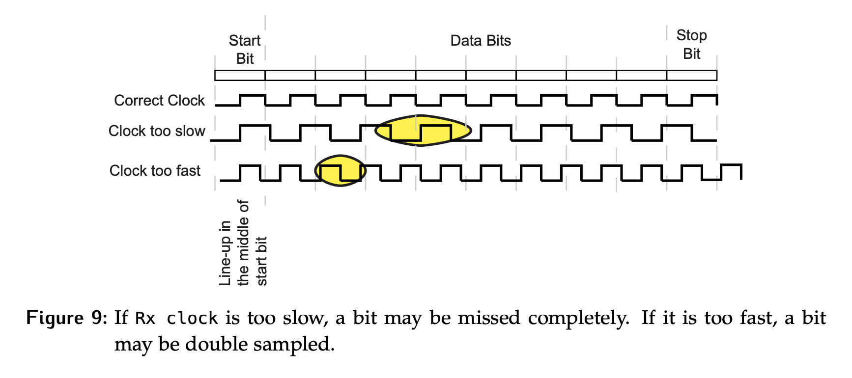
Why is 0.5 bits the acceptable variance? Since the target sample location is the middle of a bit, a shift by 0.5 bits either way will result in a bad sample.
Let and be the actual clock rates for the transmitter and the receiver respectively as shown in Figure 10. The number of bits to be transferred without error is (includes the start and stop bits). If , then the shift at the end of bits is larger than 0.5 bits.
Therefore, the frequencies of the derived clocks at the receiver and the transmitter must differ by no more than 5% (for a 10 bit frame). If we have more bits, the required clock precision is increased; the more bits to be transmitted, the tighter the tolerance required to guarantee drift does not exceed half a bit.
Start Bit Error
When the line is sampled half a bit time after the edge of the start bit is detected, the value is expected to be zero. If it is not, a start bit error has been detected. This probably indicates that a false start bit has been detected; for example, the data line dropped low momentarily due to noise or cosmic radiation. Alternatively, there may be some error in the assumed bit rate.
Framing Errors
Framing errors indicate an incorrect frame has been detected. In the case of one-byte asynchronous transfers, the symptom of a framing error is incorrect stop bit(s). This could be caused by mismatched baud rate settings on the two sides or a frequency difference between the sides that exceeds the allowed tolerance.
Parity Error
A parity error occurs if the parity of the received data and the parity setting do not match. For example, the received data has odd parity but the receiver is set for even parity. The data will be thrown away, but whether or not it is resent is not specified by the protocol. It will depend if the user has built a mechanism to confirm receipt or not.
Parity
Parity is a method to detect errors in transmitted data. It involves adding an extra bit, known as the parity bit, to a set of data bits to ensure that the total number of 1s in the set (including the parity bit) is either even or odd, depending on the chosen parity scheme. There are two main types of parity:
- Even Parity: The parity bit is set such that the total number of 1s in the data bits plus the parity bit is even.
- Odd Parity: The parity bit is set such that the total number of 1s in the data bits plus the parity bit is odd.
Example:
- Suppose we have a byte of data:
1011001(7 bits)- For even parity, we add a parity bit to make the total number of 1s even. The data with the parity bit becomes:
10110011(8 bits, total number of 1s is 4, which is even)- For odd parity, we add a parity bit to make the total number of 1s odd. The data with the parity bit becomes:
10110010(8 bits, total number of 1s is 5, which is odd)
Overrun Error
In a serial communication system, the data at the transmitter and receiver is transferred at a time convenient to the controlling processor. As a result, the serial data may arrive too quickly for the receiver to process the data. The transmitter might also be sending data faster than the serial channel can transfer the data. In either case, some data may be overrun by the data following it in the channel. This is an overrun error.
There are two special cases:
- Receiver overrun error: At the receiver, incoming data has overwritten data in
SRinorRCVregister. There are circumstances where this can occur and be acceptable in practice. For example, if the system is dealing with a rare but high priority interrupt, the trade-off of losing a piece of data can be reasonable. - Transmit overrun error: Resulting from the CPU or the device writing to the
XMITregister before the current content ofXMITbeen transmitted. If this happens in practice, it is a sign of user error. New data should never be written toXMITbefore it is empty.
Configuration Settings Error
Another potential issue arises if the configuration settings are not the same on both sides of the channel. Consider the situation where the transmitter and the receiver use different assumptions about the number of stop bits (SB) as illustrated in Figure 11. Note that a similar issue is not possible related to the start bit since all systems use 1 start bit and there can be no setting mismatch for this part of the protocol.
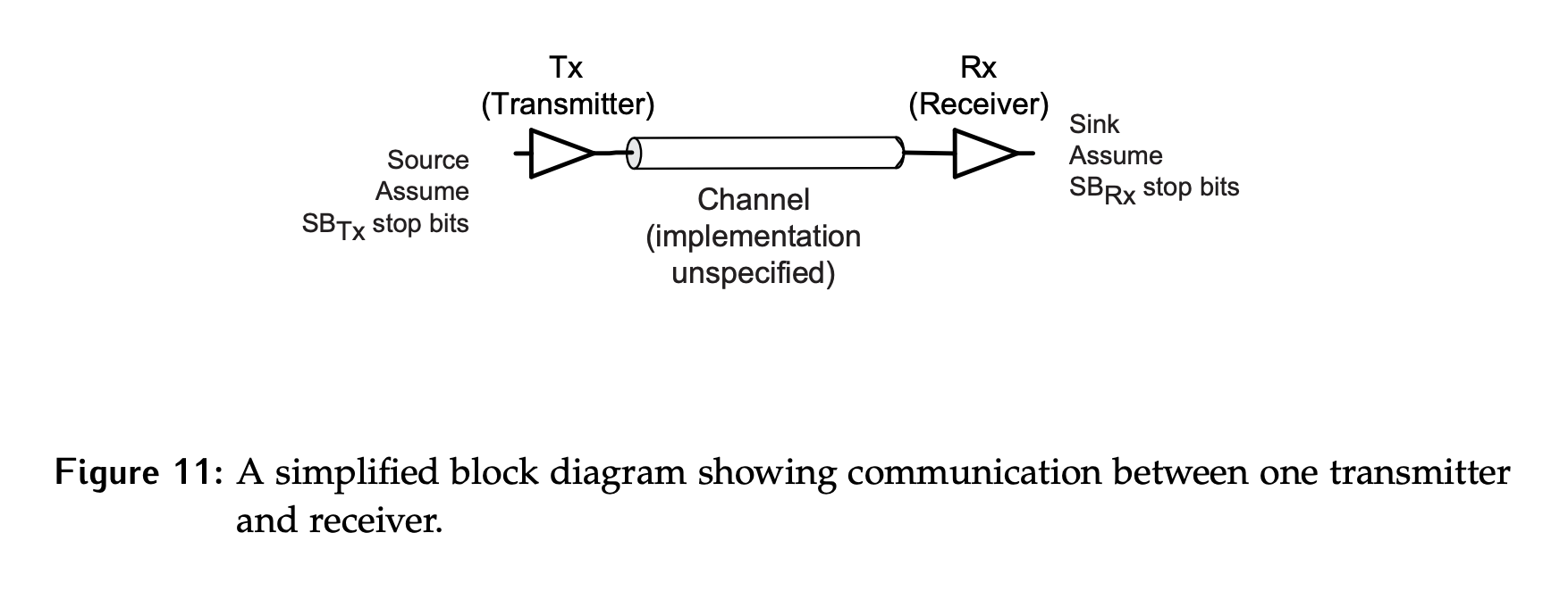
- If , there is no problem.
- If there may be a bit of extra idle time between consecutive bytes, but communication will not be a problem.
- If , there is a problem. If the transmitter ever sends consecutive bytes as close together as possible (less than one bit time separation), then the receiver will be looking for a stop bit (1) where there is a start bit (0), and a framing error would be detected.
If the channel is bidirectional, then in most cases the number of stop bits used for the transmit and receive timing on the same device will be the same. Hence, if there is a discrepancy, one direction of communication will have the relationship while the other will transfer successfully.
Error Checking Order
There is an order in which these errors are checked.
- If a start bit error is detected, there is no need to continue receiving the rest of the frame, it is invalid so the transaction is stopped.
- If a framing error is detected, the frame is discarded.
- The parity is only checked if there is no start bit error or framing error.