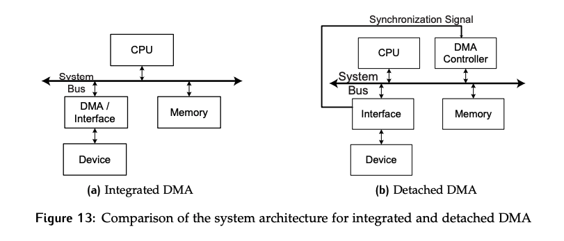
The integrated DMAC had the advantage of reducing the number of bus cycles to transfer a piece of data from 2 to 1, but the drawback of only being usable for block transfers that involve the device it is integrated with. An alternative is to use a controller that is a standalone peripheral. This is known as a detached controller. We will specifically discuss the dual-address detached DMAC. The figure below compares the integrated and detached implementations.
The detached DMAC acts as a surrogate CPU. It is called “dual address” because a read needs to be followed by a write to completely a single transfer; therefore, both the source and destination address are required.
There are additional registers required in the detached interface compared to the integrated case, which have been highlighted in yellow in the figure below.
- The
bufferacts like theMDRin the CPU - The
DIARis the device interface address register. It is used to store the address of the next location to be accessed in the device.
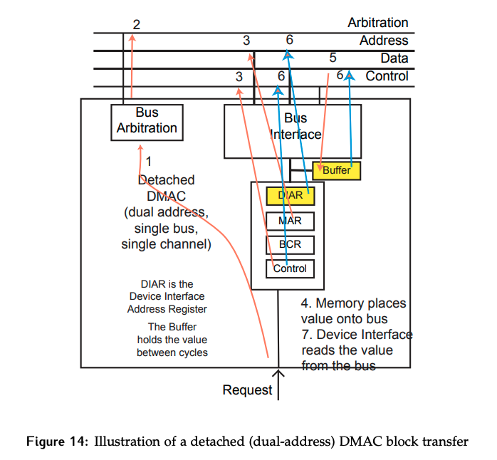
Assuming the DMAC is operating in cycle stealing mode (transfer of 1 byte per bus controllership), and block initialization has already been completed, the transfer of one unit of data will be as follows:
- DMAC receives a request from the device.
- DMAC participates in and successfully arbitrates for control of the bus.
- DMAC initiates a read from the memory address stored in the
MAR(or the device address stored in theDIAR). In other words, the control phase of the synchronous bus read cycle is completed. - Memory (or device) places requested data on the bus; in other words, the peripheral phase of synchronous bus read cycle is completed.
- DMAC temporarily stores the data to be written in the
buffer. - DMAC writes the data to the device at the address stored in the
DIAR(or memory); in other words the controller phase of the synchronous bus write cycle is completed.
This requires twice as many bus cycles as the integrated version of the transfer, but no hardware changes to device interfaces.
Why bother if the number of cycles is the same?
Each DMA cycle requires 2 bus cycles, a read and a write. This is the same amount of cycles that are required for the data transfer portion of the programmed controlled input and output (CPU driven case). So why bother with using a detached DMA at all?
While the number of transfers has not been reduced, there are still significant savings from the CPU perspective as it no longer needs to be involved with the transfers.
System Bus View
Consider which entities are driving signals on the synchronous system bus.
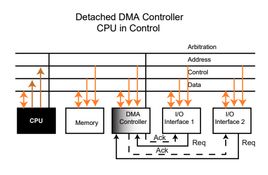
If the CPU is currently bus controller, it will drive the address and control lines. All other entities, including the DMA controller, will only be listening to these lines. This is shown below; the diagram shows a detached controller, but the scenario would be the same in the integrated case.
- When the CPU is in control, the DMAC is just another peripheral in the system.
- The data lines to all entities are bi-directional to support reading and writing data to any address in the system.
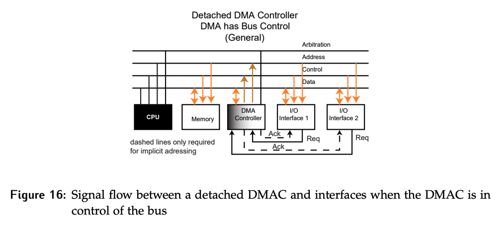
If the DMAC is currently bus controller, the CPU will have no involvement with the bus. The DMAC is now responsible for driving the address and control lines as shown in Figure 16. From the perspective of the peripherals, nothing has changed. They cannot tell the difference between a transaction controlled by the CPU and one controlled by the DMAC.