In a character-oriented serial interface, there can be errors in the system that cause data corruption. Two common causes of corruption are noise in the channel, and timing problems such differences in clock frequencies between the two end points. The magnitude of allowable error related to the phase shift and frequency between the Tx Clock and Rx Clock signals.
Consider a simple serial system with two endpoints, a transmit Tx endpoint and a receive Rx endpoint.
- The
Tx ClockandRx Clockon a given interface do not have to be at the same data rate, but in practice they typically are. - In many of the diagrams in this section, the clocks are drawn as external to the interface, but the reality is the precise source rarely matters. It may be a local oscillator dedicated to the interface, a clock derived elsewhere in the chip or a clock sources from outside the chip completely.
- Whether or not both the
TxandRxendpoints have visibility of the same signal is the determining factor for asynchronous vs. synchronous communication.
Motivation for Asynchronous Case
As shown in Figure 4, there may be up to 4 clocks or oscillators in this system if each endpoint has separate transmit and receive clocks, and data is being transmitted asynchronously. Thus, for the asynchronous case, we need to think about clock phase alignment.
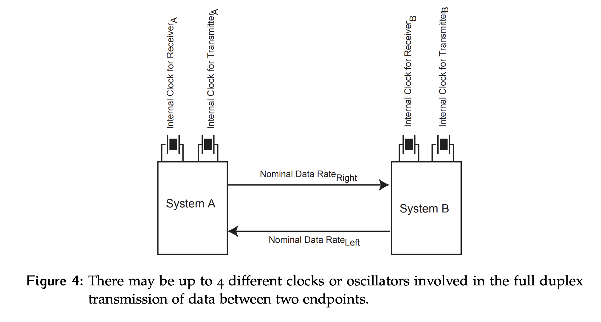
Consider system A as the transmitter and system B as the receiver; even if the two clocks have perfectly matched frequencies, how can the system ensure that sampling occurs at the correct time?
The two clocks are completely independent, so simply saying something like transmit on the rising edge and receive on the falling edge doesn’t help. If the clocks are out of phase with each other these edges will occur at the same time!
Why do we care about the middle of the bit?
By sampling in the middle, the receiver maximizes the tolerance for any slight timing differences or clock drift between the two devices. Thus, it is the optimal point within the duration of a single bit period where the receiver should sample the incoming data to minimize errors.
One common solution is to run the Rx clock at a multiple of the transmit frequency, typically or . This introduces the need to determine which edges to care about and which to ignore, but ensures that there is an edge close to the middle of the bit.
Example
To see how running the receive clock at a multiple of the transmit clock works in practice, consider Figure 5. In this scenario, the sender is changing the data on the falling edge of the Tx Clock. We assume propagation delay can be ignored, so that a change at the sender can immediately be seen by the receiver.
Three possible Rx clock frequencies are considered here: , and of the Tx Clock. For each frequency, we also consider 3 possible phases of the Rx Clock relative tot he Tx Clock.
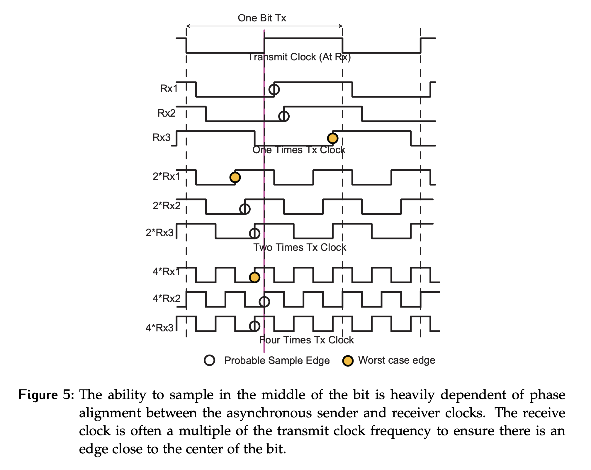
The receiver is sampling data on a rising edge, so a circle has been used to mark the rising edge closest to the center of the transmitted bits (which corresponds to the rising edge of the Tx Clock) for each of the possible receive clocks.
Considering the worst case errors with respect to “bit time”, which is the duration of time that it takes to transmit or receive a single bit of data.
- If the
Rx Clockfrequency is the same asTx Clock, the worst-case error is of bit time. - Increasing the
Rx Clockfrequency to means double the edges are available, so the worst-case error is reduced to bit time. - Doubling again to of
Tx Clockreduces the error to . - This continues with larger multiples.
Guaranteeing an edge close to center is great, but what about all the extra edges this introduced? When the character-oriented asynchronous protocol is examined in more detail, it will be shown that some mechanism for phase alignment is needed to identify the edge of the bit. From there, clock edges can be counted and sampling is only done at counts that correspond to the center of bits.