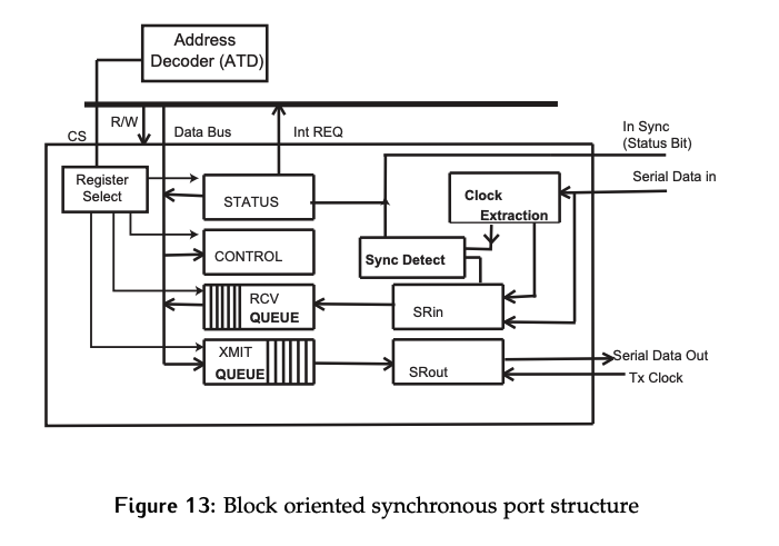
In order to support synchronous communication, some modifications to the hardware used for the asynchronous case are necessary.
- The
RCVandXMITregisters are replaced with queues.- Since data rates are higher, these queue provide buffering, so that we can stage an entire block or blocks of data for transmission, or receive and re-assemble an blocks without requiring very precise and time-sensitive interactions with the CPU.
- Some protocols can handle gaps within a block of data, in which case smaller queues can be used.
- Clock Extraction and Sync Detect hardware have been added.
- While the queues are always required, these are only needed if the protocol embeds clock information into the data.
- In this case, a local oscillator is still needed for receiving data. Just like an oscillator at a higher multiple of the transmit clock was used for phase syncing in the asynchronous case (see here), it can be used for phase synchronization on the recovered clock signal.
Start and stop bits used to define a transfer in the asynchronous case are no longer used, so additional hardware and alternate methods are now required to achieve bit, byte, and block synchronization.
Clock Extraction
How can the clock be recovered from the received signal?
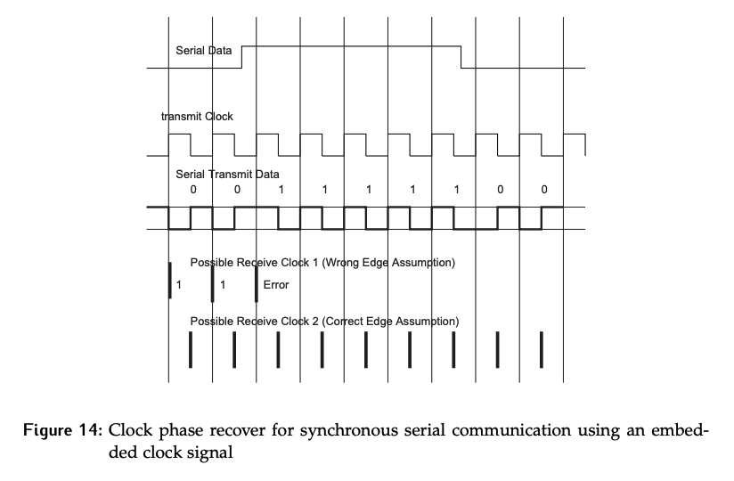
Recall that in Manchester encoding, the first half of the bit time will be the logic value, while the second half is the inverse. So, a logic 0 is low-high, and a logic 1 is high-low. This ensures there is a transition in the middle of every bit. Assuming the data is being sampled on the rising edge of the transmit clock, the Manchester encoded data is show on the third line of the figure below.
On the receive side, edge detection is used. Bit rate synchronization is done by agreement, but we still need bit phase synchronization.
Once an edge is identified, the local oscillator is used to count for 3/4 of a bit time, then a sample is recorded.
- Why 3/4? Since the edge is in the middle of the bit, and the goal is to sample in the middle of valid data. This means that the edge detected is being used to achieve phase synchronization for the next bit.
Once the bit is sampled, count another 1/4 of a bit and check for the next edge.
- If the edge is there, it acts to reset the counter to 0 and in turn resets the phase error. Then, begin counting to 3/4 again. This case is illustrated in the 5th line of Figure 14.
- If the edge is not there, the system knows it has the wrong edge. It has started on a transition between back-to-back bits of the same value and not the middle of the bit. In a real system, the data red so far would be discarded, and it would count forward by 1/2 bit time and restart the whole process from that edge instead. This means some amount of disposable data is required for phase synchronization to be achieved before real data is sent when the clock is embedded. This case is illustrated in the 4th line of Figure 14.