We discuss a simple character-oriented interfaces, where data is transferred one character (or byte) at a time. Here, “serial interface” means that we are talking about the internal interface that manages serial communication, not the simple external serial wire connection itself.
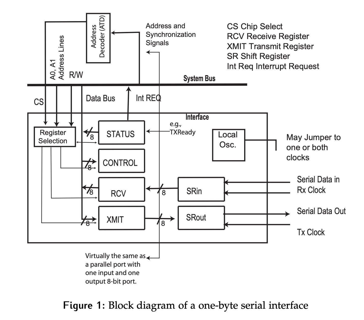
The hardware needed to build serial interfaces is minimal, we just need a parallel port interface, with two extra registers. Figure 1 shows the parallel port interface that connects to the system bus which connects to the CPU.

- The control register is used by the CPU to send non-data information to the interface, while status is used by the interface to communicate non-data information to the CPU. These are standard parallel port registers.
- The final two registers of the parallel interface are used for data, which are known as transmit (
XMIT) and receive (RCV) the serial interface. These are the same as the DO and DI in a parallel port. - The additional hardware required to add serial support to the interface consists of two shift registers: serial in (
SRin) and serial out (SRout). TheTxandRxlines are the data lines through which the serial data is transmitted or received to the registers. - Depending on whether an asynchronous or synchronous clocking scheme is used, as well as the desired clock source, a local oscillator may also be required.
Interface → Peripheral
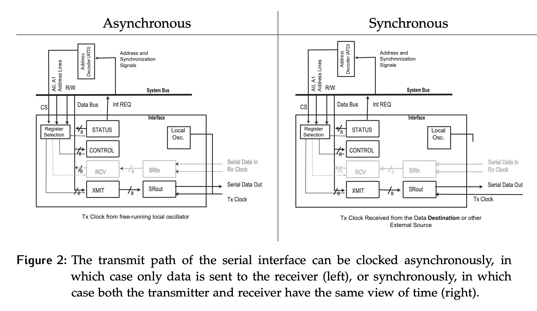
Consider the process for data transfer from the serial interface to the peripheral:
- Data is loaded into transmit (
XMIT) register in parallel from the system bus. - When the serial out (
SRout) register is idle, data is transferred fromXMITtoSRoutin parallel. - Data is shifted out serially from the serial out (
SRout) register by the transmit (Tx) clock.
How is data shifted out of the SRout register?

- In the asynchronous case on the left, the local oscillator is used to shift the data out of the transmit register. This clock signal is NOT shared with the receive side.
- If it is shifted synchronously, the clock information is transferred with the data. In most cases this will mean a second wire carrying the clock signal, although we can also embed the clock information into the data. The source of this clock signal could be anywhere in the system, including the local oscillator of the transmitter. It is synchronous because both the transmitter and receiver are sharing a view of time, not because of where the clock source is physically located.
Peripheral → Interface
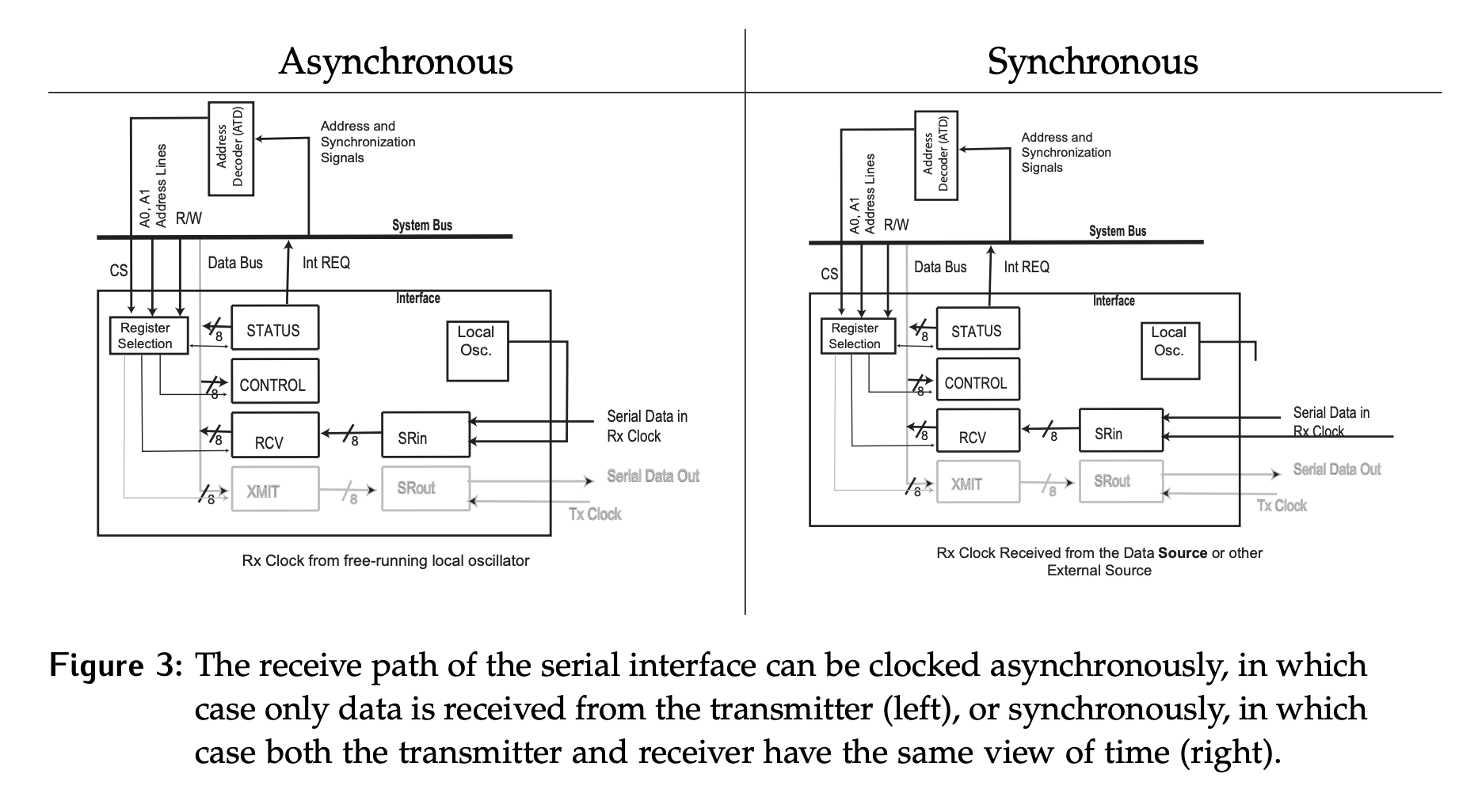
Now consider the path taken by the data when it is transferred from the peripheral to the serial interface:
- Data is shifted into the serial interface in the
SRinregister using the receiverRxclock. - When
SRinis full, data is transferred into the receiveRCVregister in parallel. - Data is transferred from
RCVto the system in parallel.
How is data shifted into SRin?

- In the asynchronous case on the left, the local oscillator is used to clock the data into the receive register.
- Since the clock information is not transferred with the data, some extra work is needed to find where the middle of a bit is and sample appropriately. How this can be done will de considered in detail later.
- If synchronous communication is used, the clock information is transferred with the data as illustrated on the right side.
- The source of this clock signal could be anywhere in the system, including the local oscillator of the transmitter or receiver. It is synchronous because both the transmitter and receiver are sharing a view of time, not because of where the clock source is.
Asynchronous vs. Synchronous Classification
In general, serial communication is classified based on the clocking scheme used.
- Synchronous: Both
RxandTxuse the same clock (frequency and phase). - Asynchronous:
RxandTxhave independent clocks that have the same (or similar) frequencies.