Empirical methods for determining endurance limits, like the rotating-beam test are unrealistic for real life.
- Endurance limit based on testing (i.e., empirical data):
- Endurance limit adjusted for specific factors:
There are some factors that can affect endurance limit:
- Material – composition, basis of failure, variability
- Manufacturing – method, heat treatment, fretting corrosion, surface condition, stress concentration
- Environment – corrosion, temperature, stress state, relaxation times
- Design – size, shape, stress state, speed, fretting, galling
Marin’s equation provides various correction factors for these:
where:
- is the surface factor
- is the size factor
- is the load factor
- is the temperature factor
- is the reliability factor
Surface Factor,
The surface factor accounts for the fact that actual parts rarely have a surface finish as smooth as the polished test specimen. Surface roughness creates many localized stress concentrations, leading to localized plastic strain at the roots of surface imperfections, causing crack initiation.
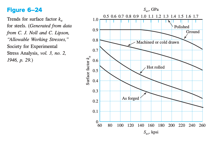
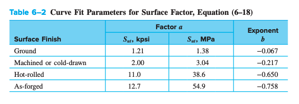
The surface factor can be curve fitted with:
Size Factor,
The endurance limit of specimens has been observed to decrease as specimen size increases for bending and torsion loads. Fatigue is dictated by the “weakest link” in the material; the probability of weaknesses in the material increases with material volume.
For round rotating bars subject to bending and torsion:
For round rotating bars with axial loading, there is no size effect, so .
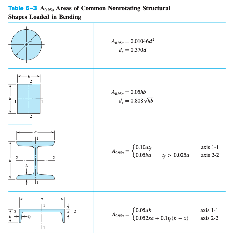
For non-round, non-rotating parts, we need to find an equivalent diameter. This can obtained by equating the volume of material stressed at and above 95% of the maximum stress to the same volume in the beam specimen. When volumes are equated, the lengths cancel out and we are left with the cross-sectional area. For a rotating, round section, 95% stress area is the ring on the outside diameter (inner diameter of , outer diameter of ):
For non-rotating, round sections, 95% stress area is
And thus, the effective diameter is .
Load Factor,
Endurance limit values are typically obtained from testing with completely reversed bending. With axial or torsional loading, fatigue tests indicate different relationships between the endurance limit and the ultimate strength for each type of loading. This can be expressed by the load factor:
The load factor for torsion is very close to predictions made by distortion energy theory for ductile materials.
- As such, load factor for torsion is mainly accounts for difference in shear strength and normal strength.
- We should use the torsion load factor only for pure torsional fatigue loading.
- If torsion is combined with another loading, like bending, use and managed combined loading using the von Mises stress.
Temperature Factor,
Depending on the difference between tensile strength at room temperature, at and tensile strength at operating temperature . The temperature factor is given as the ratio between the two:
For steels:
Reliability Factor,
The reliability factor accounts for scatter in endurance limit fatigue data. Most endurance strength data is reported as mean values. The endurance limit is experimentally determined to be related to the ultimate strength by . This roughly corresponds to a line through the middle of scattered data. The reliability factor allows the slope of the line to be adjusted to increase the reliability of data points being included above the line.
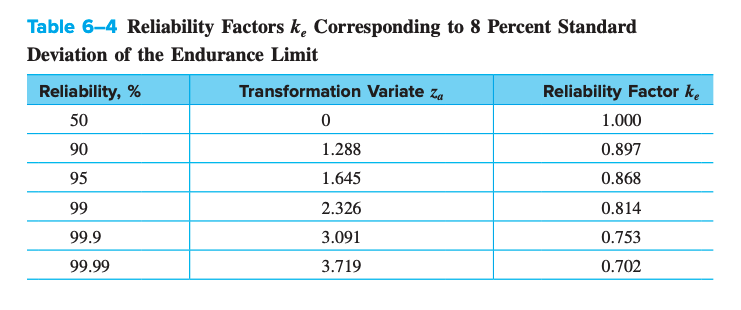
The reliability factor is written as:
where is defined by -score of the line we want to use.