Faraday’s law states that when a time-varying magnetic flux passes through a coil of wire, an emf will be induced in each turn of the wire, which is proportional to the rate of change of magnetic flux passing through the wire with respect to time.
The induced emf in each turn of wire is given by:
If the same flux passes through all turns of wire in the coil, the total induced emf will be:
where is called the total flux linkage. The negative sign describes the polarity of the induced voltage with respect to the direction of change of magnetic flux with respect to time. This negative sign is explained by Lenz’s Law.
Applications
Faraday’s law expresses the mechanism behind the operation of transformers and some generators.
Transformers
In transformers, an alternating current is passed through an -turn winding (called the primary winding), leading to a time-varying flux in the core. The time-varying flux passes through another winding (called the secondary winding) wrapped on the same core, which is composed of turns of wire.
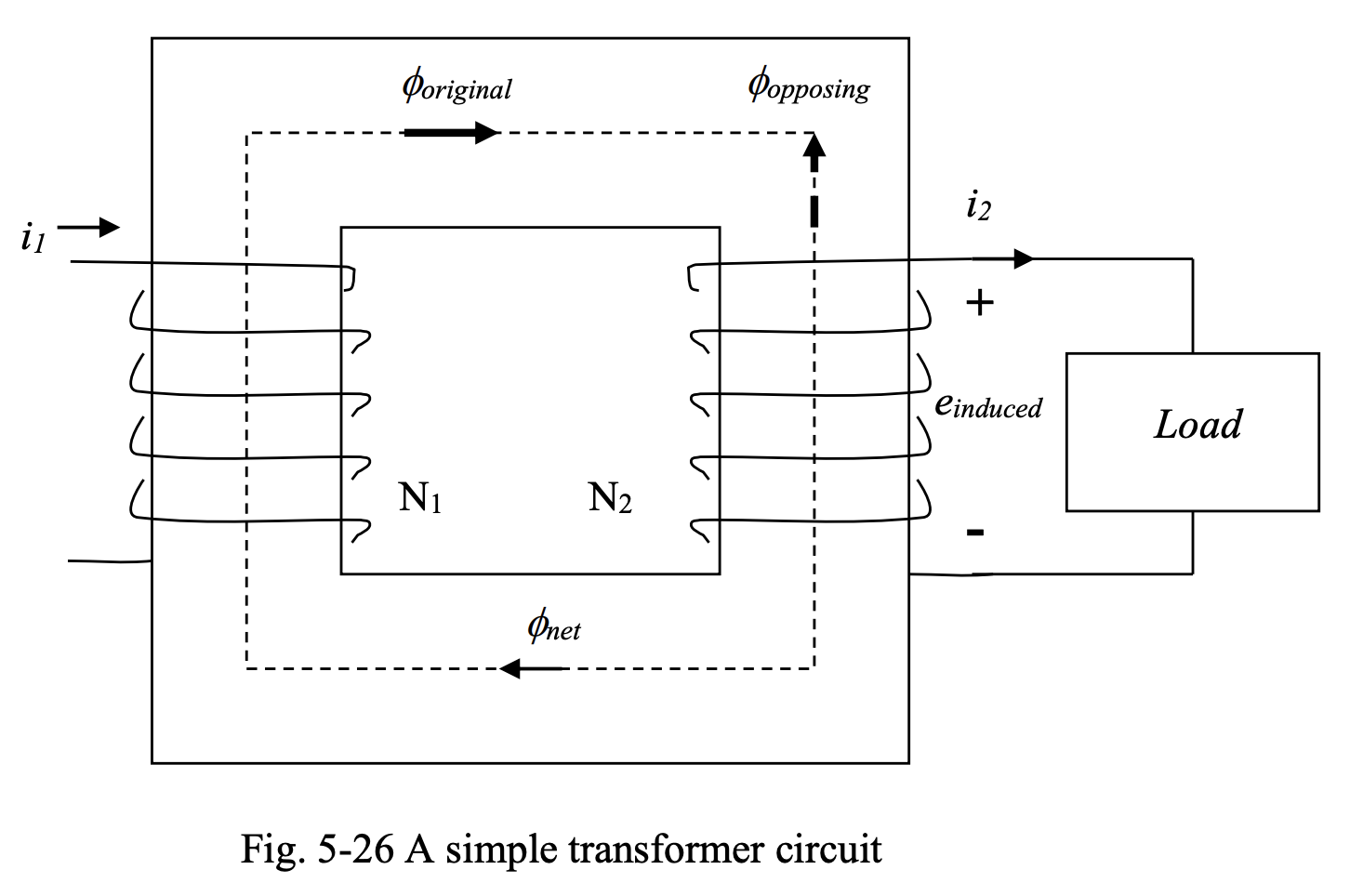
According to Faraday’s law, a voltage will be induced in the secondary winding. The polarity of this voltage will be such that the current produced in the secondary windings, when a load is connected across the secondary terminals, will result in a flux that opposes the changes with respect to time in the flux that generated it. For example, in the case of a sinusoidal flux , when the flux is in the positive half cycle and increasing with time, the induced voltage will have the polarity shown in Figure 5-26, so that the current produced when the secondary terminals are loaded, results in a flux that opposes the rise of the original flux.
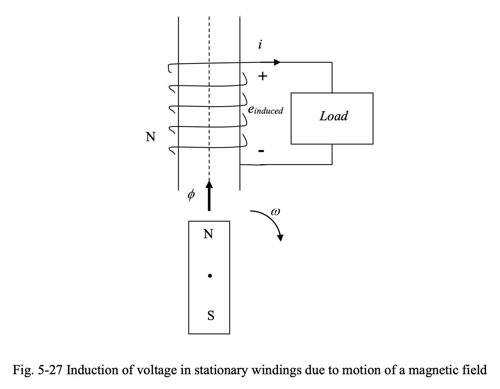
Synchronous Generators
In synchronous generators, a permanent magnet or an electromagnet on a rotor (moving part) generates a magnetic field. As long as the rotor is at a standstill, the coils of wire installed on the stator (stationary part) do not see any variations in the magnetic flux. As a result, based on Faraday’s law, no voltage will be induced in the stator windings. When a motor is rotated, the magnetic field, even though constant in magnitude, will be changing with from the point of view of the stator windings.
This results in the induction of an emf in the stator windings. This voltage will appear at the generator terminals. This is the mechanism of generation of electricity in synchronous generators, which are the generators commonly used for bulk generation of electricity in the power systems.
The magnitude of the induced voltage is proportional to the number of turns of wire. Thus, in generators, a rather large number of turns of wire is used to generate a high enough voltage for the intended application.