We can use Thevenin and Norton equivalents to capture the most important details of a circuit when considering how it can be connected to other circuits, which is especially true for modeling loading (when the output of one circuit expends energy providing a signal to the input of another circuit).
Consider an op-amp voltage buffer whose output voltage is , where the output voltage copies the input voltage. The input terminal requires almost no current, so a weak signal can be reproduced without degrading it. The opamp repeats this signal but can provide a much higher current, , to connected circuits modeled in the figure as a load resistor, .
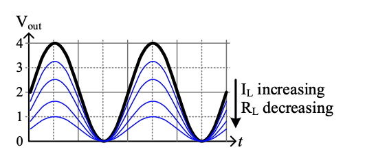
- Ideal “no load” output voltage in black, meaning that the opamp doesn’t need to provide any current.
- As increases, modelled by decreasing , the opamp struggles to produce the necessary output voltage, and it drops.
- Voltage drop is called “load regulation”, a type of loading effect that changes a circuit’s behavior when connected to (loaded by) another circuit. Loading effects must be modelled when designing hardware systems or they will likely fail in the context of the system in which they were embedded.
- Thevenin and Norton Representations can capture the necessary behavior.
Op-amp example
Consider a generic voltage amplifier circuit (shown here with opamp symbol).
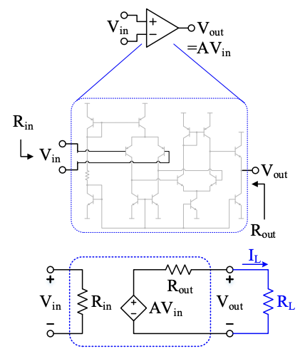
is applied to the input terminals and . In the previous example, the simple voltage buffer had since it was a simple voltage buffer.
- How much current needs to go into the input terminals?
- How much current can the output deliver?
These answers depend on what circuit composes the amplifier, what devices are used to build the circuit, how the circuit is packaged, etc. The op-amps used in embedded systems are typically integrated circuits with multistage transistor amplifiers. The input terminals may be connected to MOSFETs requiring minimal current, BJTs requiring some small current, or other devices depending on the application. The output may be driven by a high-power output stage that can deliver very high current or a low-power output stage that is very efficient instead.
Regardless of the circuit specifics, input and output loading effects can be modelled as and and neatly summarized in a model that uses Thevenin equivalent circuits as input and output. The input Thevenin equivalent voltage is (a short circuit) since the open-circuit voltage at the input is zero when nothing is connected. The output Thevenin equivalent voltage source is now a dependent source to model how it depends on the applied input voltage.
With this model, the drop in output voltage as current demands increase can be much easier to understand as a voltage divider between and : as drops, more of the applied voltage is dropped across instead of appearing at the output terminals.