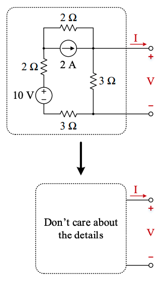
The goal of these representations is to simplify a circuit to only understand the behavior of the circuit (inputs and outputs) and abstracting its inner workings.

Thevenin Equivalent Circuit
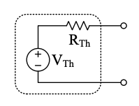
A series voltage source and resistor is called the Thevenin equivalent circuit, with:
- Thevenin equivalent voltage,
- Thevenin equivalent resistance,

Norton Equivalent Circuit
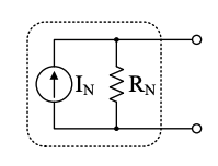
A parallel current source and resistor is called the Norton Equivalent Circuit, with:
- Norton equivalent current,
- Norton equivalent resistance,

The two forms can be quickly interchanged by remembering that the terminal voltages and currents are equivalent, which leads to the following relationships:
This is explained below:
Source Transform
Linear circuits can be reduced to two forms:

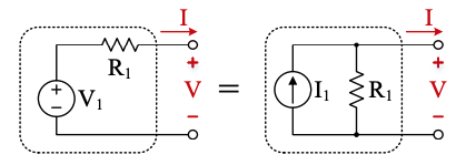
We can flip between these two forms during analysis because the voltage and current behavior at the terminals is identical, called a source transform. Consider the two extremes of applying open-circuit and short-circuit conditions at the terminal:

The left case is for creating a voltage source at the terminal and the right case is for a current source at the terminal.
- In the open-circuit case, is measured at the terminals of both circuits, with on the left and on the right.
- In the short-circuit case, both output a current of , with on the left and on the right.
- Since these circuits are equivalent, therefore . We can use this relationship to convert between the two forms without changing terminal behavior