RLC Circuit
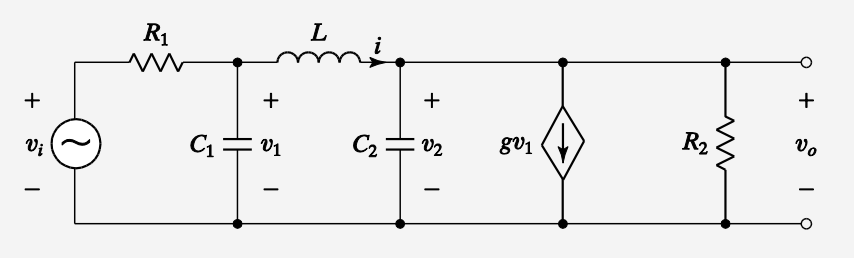
- is a voltage-controlled current source
We have:
- Input and output of and
- Intermediate variables: Capacitor voltages and , and inductor current
Then, we write down independent differential equations using Kirchhoff’s current law (KCL) and Kirchhoff’s voltage law (KVL), applied to nodes and loops involving inductors and capacitors.
KCL:
- Node 1 (between and ):
- Node 2 (above ):
KVL:
- Loop 1 (with ):
The output can be written just as:
Re-writing everything:
In matrix form:
and