The basic elements of a motor, like that shown below, are the stator, the rotor, the armature, and the commutator.
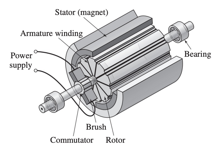
- The stator is stationary and provides the magnetic field.
- The rotor is an iron core that is supported by bearings and is free to rotate.
- The coils are attached to the rotor, and the combined unit is called the armature.
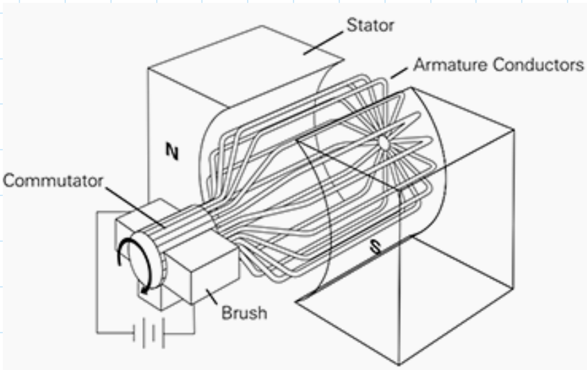
As a coil rotates through the torque will reverse direction unless the current can be made to reverse direction also. In addition, a means must be found to maintain electrical contact between the rotating coil and the power supply leads. A solution is provided by the commutator, which is a pair of electrically conducting, spring-loaded carbon sticks (called brushes) that slide on the armature and transfer power to the coil contacts.
The electrical subsystems of the motor can be represented by the armature circuit and the field circuit shown below. In a permanent-magnet motor, the field circuit is replaced by the magnet.
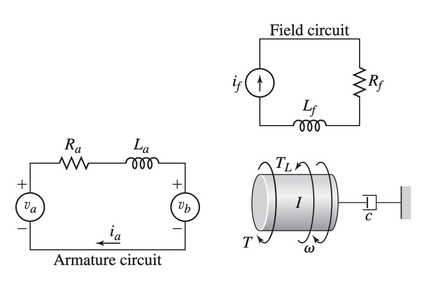
- – Input voltage to armature
- – Counter emf generated by motion of armature (opposes the current)
- – Opposing torque of load
- – Generated torque
- – Number of armature coils
- – Length of each coil
- – Radius of the rotor (armature)
The force on the armature due to magnetic field is:
Then, the torque produced by the motor is
where is the motor’s torque constant.
As we have seen, the motion of a current-carrying conductor in a field produces a voltage in the conductor that opposes the current. This voltage in the armature is called the back emf (for electromotive force, an older term for voltage). Its magnitude is proportional to the speed. The coils’ linear velocity is related to their angular velocity by . Thus:
Note that .
System Model
Kirchhoff’s voltage law gives
Newton’s law applied to the inertia gives
The two equations above constitute the system model.
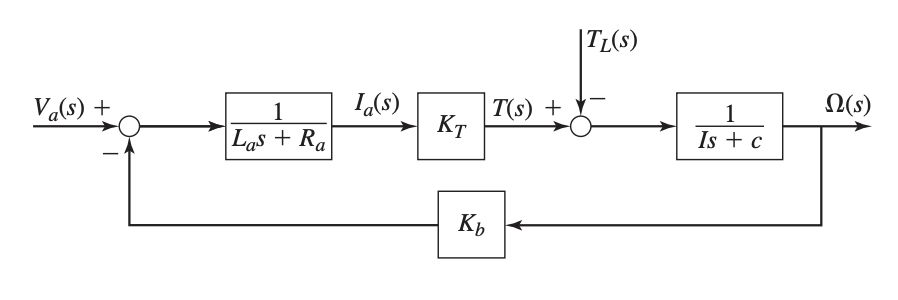
We can convert to Laplace domain:
Re-arrange:
Solving:
This can be drawn as a block diagram:
Transfer Function
Normally we are interested in both the motor speed and the current . The two inputs are the applied voltage and the load torque . Thus, there are four transfer functions for the motor, one transfer function for each input-output pair:
We can obtain these transfer functions either by reducing the block diagram shown above, or by solving the equations above.
State-Variable Form of Motor Model
The above system model for the model can be put into state variable form by isolating the derivatives of the state variables and . The system equations were:
Isolating:
Let and . Then we have:
In matrix form: