In the serial communication context, encoding refers to how the data is represented.
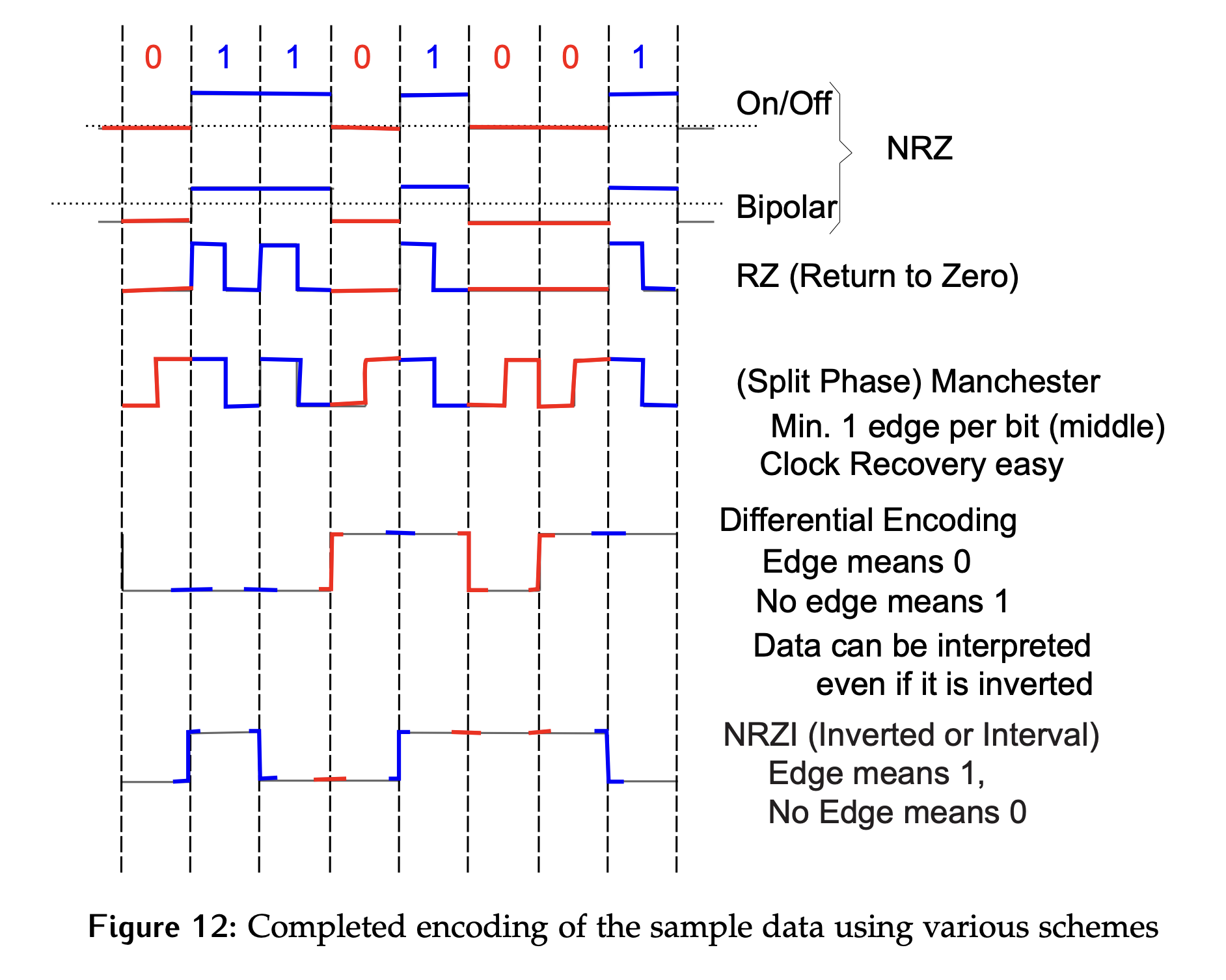
On/off encoding is a typical method that we see often, where a logic value of 0 is mapped to , and a logic value of 1 is mapped to some higher voltage, like or .
Bipolar encoding also represents logic values with voltage levels, but they are now centered around . For example, logic 0 might be , while logic 1 might map to .
Return to Zero (RZ) encoding uses the second half of every bit time as a “rest” phase. The value during the second half of every bit cycle will be 0 and the data value is really only encoded in the first half of the bit. This can be handy for error checking, and the edge in the middle of a 1 can be used for synchronization purposes in some protocols.
- As a general note, encoding schemes that do not have a rest point are referred to as non-return to zero or NRZ schemes. Both the on/off and bipolar schemes fall into this category.
Manchester encoding encodes the clock information with the data by always forcing there to be an edge in the middle of the bit. The first half of the bit time is the value as it would have been sent using the on/off encoding scheme. The second half of the bit time is the inverse. For a logic 0, the signal will be for the first half of the bit time, then the value of a logic 1, say , for the second half of the bit time. Having this edge in the middle of every bit allows the recovery of a clock signal.
Differential encoding no longer uses the level of the signal, it is the edges that matter. An edge represents a logic 0, and no edge is a logic 1.
- Looking at the bits to be encoded in Figure 10, the first bit is a 0 so it is represented with an edge. The second bit is a 1, so there is no edge. The next bit is a 1 so no edge. The fourth bit is a 0 so an edge is needed.
- A really common mistake when learning differential encoding is confusing the edge based on the bit itself with an edge based on a transition in the binary value to be encoded.
- For example, between the third and fourth bits the transition isn’t happening because the binary value went from a 1 to a 0, it’s transitioning because the fourth bit is a 0.
- The fact that this scheme is based purely on edge or no edge and not the level itself means that the same bits could have been encoded with a horizontal mirror image of this signal. In other words, the trace could have started at 0 V, risen to the high voltage level and stayed at that value for the second bit and it would be an equally valid encoding if the initial voltage wasn’t known.
Non-return to zero inverted (NRZI) encoding is the opposite of the differential encoding scheme. In this case, an edge is going to represent a 1 and no edge is going to represent a 0.
- Once again the horizontal mirror image of the signal would also be valid. In this case, the first bit is a logic 0 so there is no edge. The assumption is being made that the previous signal value was 0 V when this data transmission. The first logic 1 causes a transition, which would be followed by another transition as the next bit is also a 1 if the trace was continued.