Just like synchronous parallel protocols, synchronous serial protocols have a shared clock visible to both the data source and the destination. There are are two choices in how this clock is shared, and synchronous protocols can be categorized based on this choice.
- Option 1: Use a separate wire to carry the clock signal, as shown in Figure 12.
- Option 2: Embed the clock signal into the data and transfer both on the same channel.
- The channel is a wire, so this means one wire carries both the data and clock position.
- This can be achieved using Manchester encoding, taking advantage of the fact there is an edge in the middle of every bit.
There are several key advantages to using synchronous protocols over asynchronous ones. Asynchronous speed was largely limited by the fact that only half a bit of error could be tolerated, and that thee error was compounding as more bits were sent, since synchronization between the two sides was only achieved at the beginning of the frame. If the clock information is being shared, the two stages are syncing every single bit and the error is no longer compounding. Thus, we can send much larger data units. Block synchronization wasn’t relevant when only one byte was being sent in a frame, but is now important since data is being sent at higher rates and multiple bytes of data have meaning as a unit.
Asynchronous rates rarely exceed the 100 kbps range over short distance, while synchronous rates can be into the 10s of Gbps.
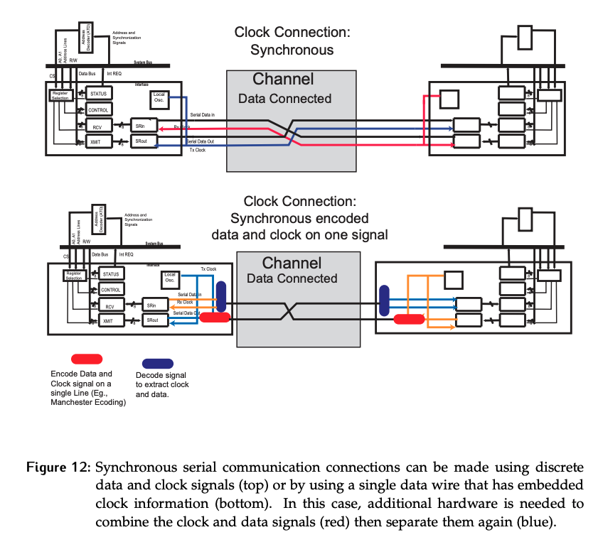
Consider how two devices connected using both the dedicated clock and embedded clock options shown in Figure 12.
In the dedicated clock, a separate wire is connected between the sender and receiver.
- It’s not uncommon for each side to have its own transmit clock, meaning the transmit and receive clocks within a given device are not the same, although they often have the same nominal frequency. Usually, the transmitter’s local oscillator is used to generate this transmitted clock signal.
- In the case of connection between only two devices, 4 wires are needed to achieve a full-duplex channel, not counting a signal ground that is required to reference the voltage levels.
In the embedded block case, only two wires are needed on the channel, again disregarding a signal ground. Additional hardware is required:
- At the output of the transmitter, we need to embed the clock signal into the data (convert from on/off encoding to Manchester)
- At the input to the receiver, we need to extract the clock information from the data and convert it back to on/off encoded data that can be used by the rest of the system.