In robotics and automotive applications, an extremely common communication protocol is CAN, which stands for controller area network.
CAN is a serial protocol that supports multiple controllers. Due to its use in automotive applications, fault tolerance is extremely important. It supports communication between the engine controller, brake controller and safety systems like air bag controllers among others, so the consequences of a failure aren’t hard to imagine. All of these controllers are capable of being bus controller. When building a vehicle, cost is also a major consideration, so minimizing the wires needed was also important.
In CAN, nodes can be connected either linearly (like how devices connect to a system bus), or they can be connected using a star topology, shown below. It’s also possible to mix the two.
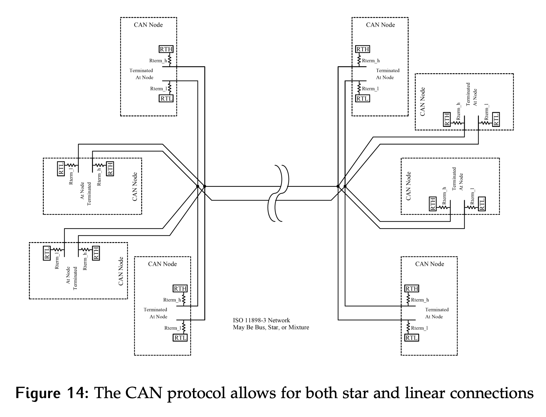
- A star topology means the wires for multiple nodes meet at one point and split to carry signals to the respective nodes.
The CAN protocol defines logic 0 to be the dominate bit and logic 1 to be recessive. This is like saying we have active 0s and passive 1s. So if both a 1 and 0 are placed on the same time, there won’t be a conflict, the line will go to 0.
CAN uses differential signals, which are less prone to noise. There are two data lines, CANH and CANL. CANL will carry the same data as CANH, but inverted.
- While considering the arbitration process, the focus will be on what is driven to the CANH line only.
- Each device will have an 11 bit ID number. The protocol does allow for what is known as extended IDs, which are just larger ID numbers, to optionally be supported.
The arbitration cycle starts when the SOF signal is sent on the bus.
- When a device wishing to use the bus sees this, it will assert the MSB of its ID on the bus.
- CAN devices have both a transmitter and a receiver. At the same time that it is asserting this first bit, it will also be monitoring the current bus value.
- If the value received is equal to the value sent, it will assert the next bit during the next bit time.
- If the received value does not equal the value sent, there is a higher priority device asking for the bus. At this point the device knows it has lost for this arbitration cycle, so it will stop trying to assert its address.
- If the device is able to transmit and read back its entire ID number, it has won this arbitration cycle and can take control of the bus to complete its transaction.
Example
Consider a sample arbitration cycle with three devices. They have addresses 0x726, 0x0F3 and 0x0F0. Table 1 shows what each device is driving to the bus at each time step, as well as what the actual value on the bus in that time step is.
0x726=(0) 111 0010 0010- The first bit is excluded because we use 11 bit ID numbers0x0F3=(0) 000 1111 00110x0F0=(0) 000 1111 0000
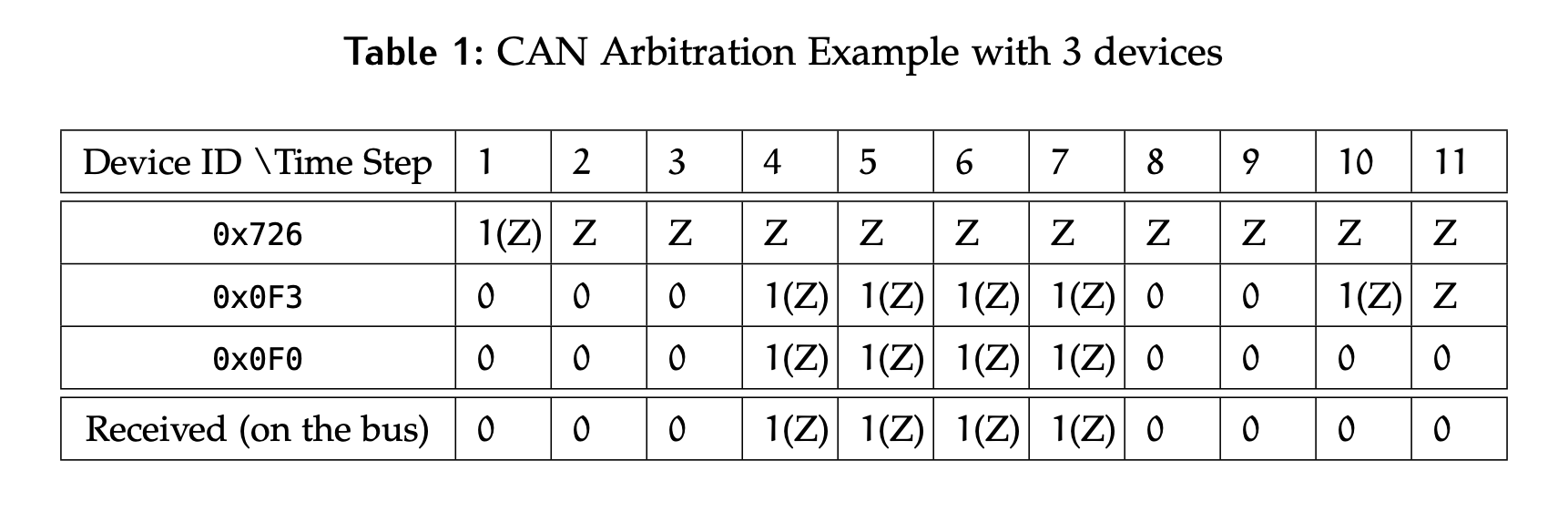
0x726loses arbitration after the first bit and defaults to sending Z.- At time step 10, device
0x0F0that wins the arbitration.
Remember that when a device has a 1 in its address, it will actually output high impedance since open drain drivers are being used. The output of the driver will also be high impedance when it is no longer participating in the arbitration cycle. To differentiate between a device that is participating in an arbitration cycle and one that has stopped, 1 (Z) is used to denote a 1 in the address that is driven as Z on the bus while Z is used for a device that has stopped participating.