Linear acceleration:
Angular acceleration:
Complex Number Representation
Recall that position is given by:
And we have:
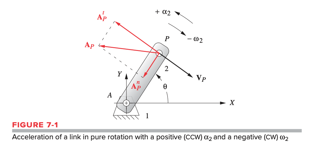
Thus, for acceleration we have:
Thus there are two terms in the expression for acceleration, the tangential component involving , and the normal component involving .
We can also write this in Cartesian form to give us real and imaginary (or and ) components of the acceleration vector:
Types of Acceleration
The acceleration above is an absolute acceleration since it is referenced to , which is the origin of the global coordinate axes in that system.
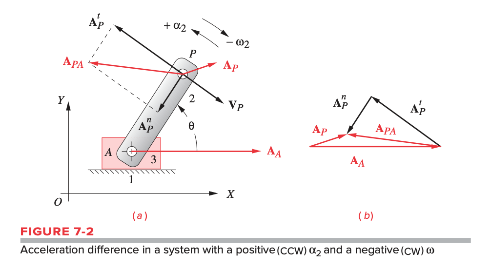
An acceleration difference is acceleration with respect to a point on the same body that is not fixed.
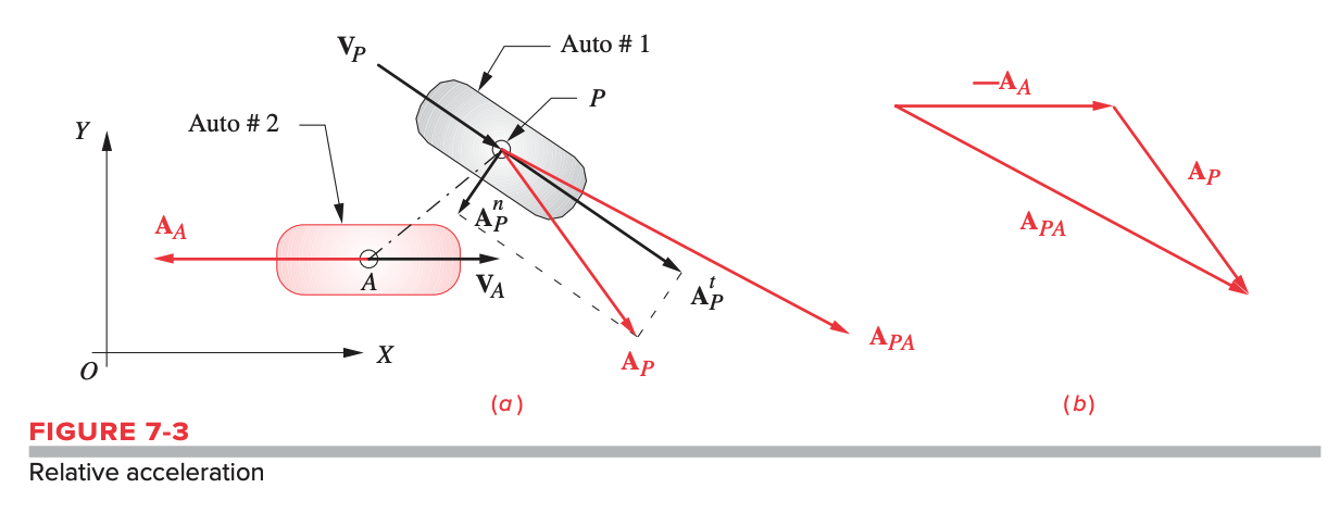
A relative acceleration is acceleration with respect to a point on a different body that is not fixed.
Vector Loop Acceleration Analysis of Fourbar Linkage
Step 1: Check the reference frame/coordinate system. should be fixed with angle of zero with respect to the -axis. If this is not the case, we need to set up a local coordinate system that meets this convention.
Step 2: Check that we have all the angles and angular velocities.
- If missing , we need to do a position analysis to find these angles (in both open and crossed configurations).
- If missing , we need to do a velocity analysis to find these angular velocities.
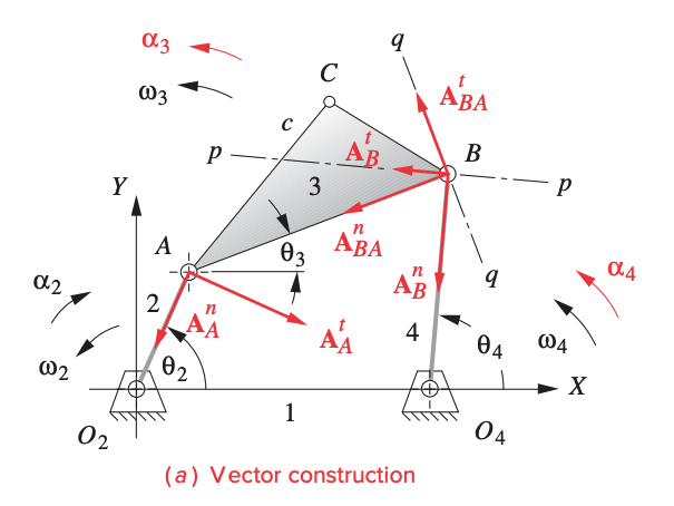
Step 3: Calculate , , :
Step 4: Calculate angular accelerations:
Step 5: Solve for the linear accelerations :
where:
- is the absolute acceleration of of link 2 with around
- is the acceleration difference of with respect to
- is the absolute acceleration of in link 4 with rotational motion about
If we need to solve for both the open and crossed positions, we will need to do steps 3 to 5 twice.
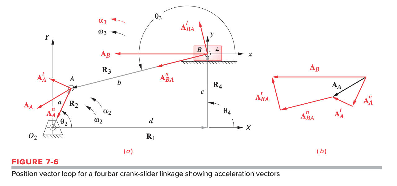
Vector Loop Acceleration Analysis of Crank-Slider
Crank is input, slider is output; similar approach to the fourbar linkage above. we use a standard representation of crank-slider for vector loop method with clockwise angular velocity of input link.
Step 1: Check the reference frame/coordinate system. should be fixed with angle of zero with respect to the -axis. If this is not the case, we need to set up a local coordinate system that meets this convention. should then be parallel to the -axis, such that .
Step 2: Check to see if we have all the angle and slider positions we need.
- If we are missing and , we will need to do a position analysis to find these parameters.
- If we are missing and , we will need to do a velocity analysis to find them.
Step 3: Calculate your angular acceleration, , and linear acceleration of slider block.
Step 4: Solve for linear accelerations :
where:
- is the absolute acceleration of on the crank about fixed point
- is the acceleration difference of the slider with respect to moving point
The acceleration of the slider is along the path of motion of the slider. The direction of its acceleration depends on if its accelerating or decelerating.
If we need to solve for both the open and crossed positions, we will need to do steps 3 and 4 twice.