An alternate approach to linkage position analysis creates a vector loop (or loops) around the linkage.
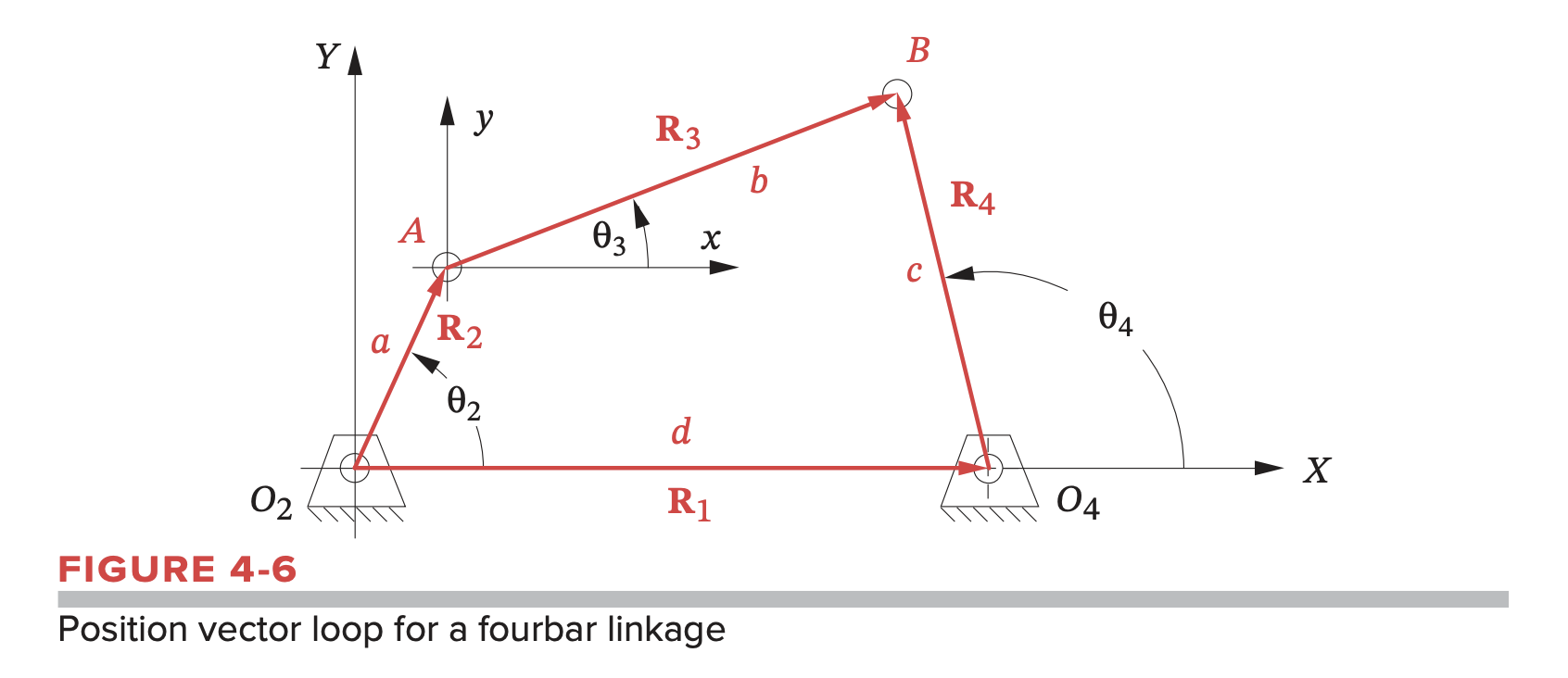
The links are represented as position vectors. Figure 4-6 shows the same fourbar linkage, but the links are now drawn as position vectors that form a vector loop. This loop closes on itself, making the sum of the vectors around the loop zero. The lengths of the vectors are the link lengths, which are known. The current linkage position is defined by the input angle as it is a one-DOF mechanism. We want to solve for the unknown angles and .
The standard representation for the vector loop method is:
We need a convenient notation to represent the vectors. This is done with complex number notation:
This comes from the Euler identity:
We can also differentiate or integrate this:
Fourbar Linkage
We have:
Note that is usually the vector of the ground link, which should be fixed with angle zero with respect to the -axis. Therefore, .
Solving this equation for and , we get:
- Positive gives the crossed configuration
- Negative gives the open configuration
- There are three possible outputs: real and equal, real and unequal, complex conjugate
- Most likely to be real and unequal
- If complex conjugate, link lengths cannot connect for chosen value of
where
and
Crank-Slider
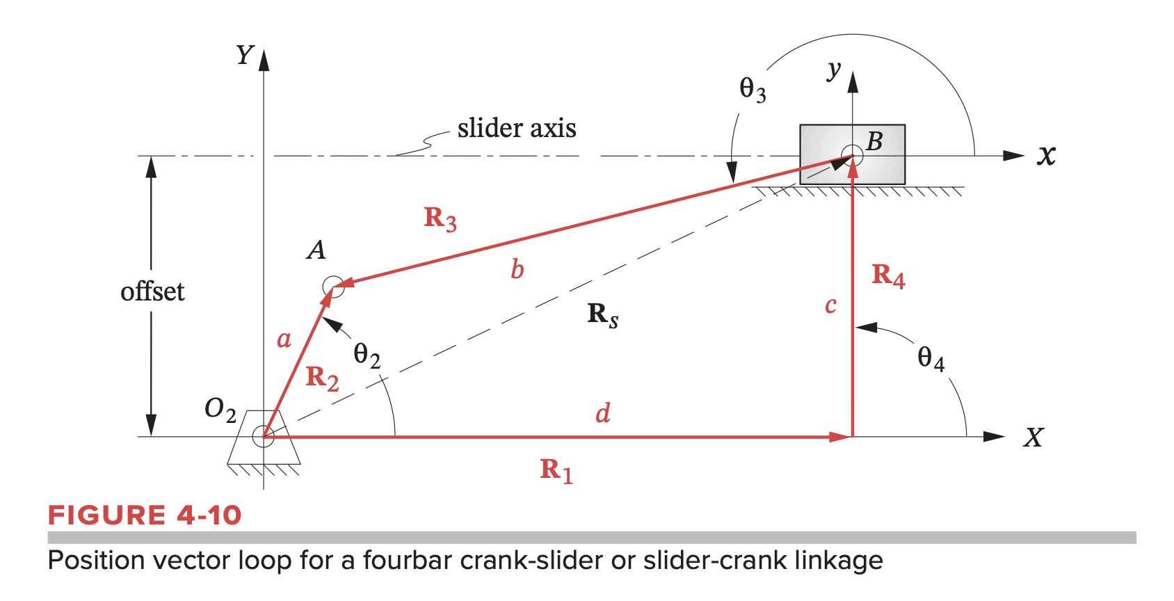
Again, we have
Note that:
- should have an angle of zero with respect to the -axis
- should be parallel to the -axis
We can then calculate one possible value for and the corresponding slider position
The other set of possible values: