A shunt DC motor cannot be started from standstill by connecting its armature across the full line voltage due to the high armature current that will result from this practice. Consider the shunt DC motor shown below:
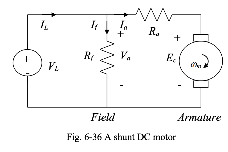
By KVL, we have:
At standstill, motor speed is equal to zero. Therefore, back emf () will be zero. As a result, can be very large and destructive. If the motor is large, is large, is small, and startup is slow due to high inertia of the rotor. In this case, the problem of high starting current is more severe.
The starting current must be limited to protect the motor and supply. A starter system is used to take care of this task. Here, a manual and an automatic starter system will be described to give an idea of how typical starter systems operate.
Manual Starter
The main component of a manual starter is a manually variable resistor, which is placed in series with the armature of the DC motor.
- At start-up, the resistor is at its highest resistance position. This results in a safe armature current when and .
- As the motor accelerates, and the speed rises, the moving arm of the variable resistor is moved, in several steps, towards the position corresponding to zero resistance.
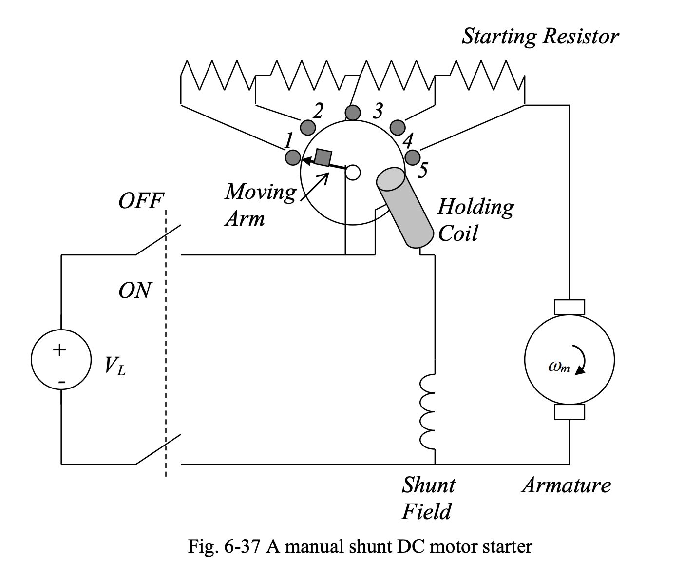
According to , as increases, due to increasing, will be limited by . Therefore, can be reduced while maintaining a safe armature current. When the starting resistance hits zero, a metal piece attached to the moving arm is attracted by an electromagnet, which is already energized through source voltage and shunt field circuit. In this way, the moving arm is held in the final position.
Below we have a plot of variations of armature current as the moving arm of manual starter is moved from position 1 to position 5 in steps.
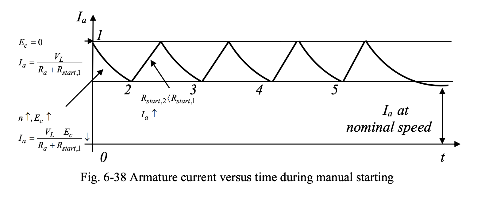
The need for a human operator and the chance of improper timing in the starting process are the disadvantages of this approach. Automatic starters solve these problems.
Automatic Starter
An automatic starter eliminates the need for a human operator and ensures proper timing in the startup process.
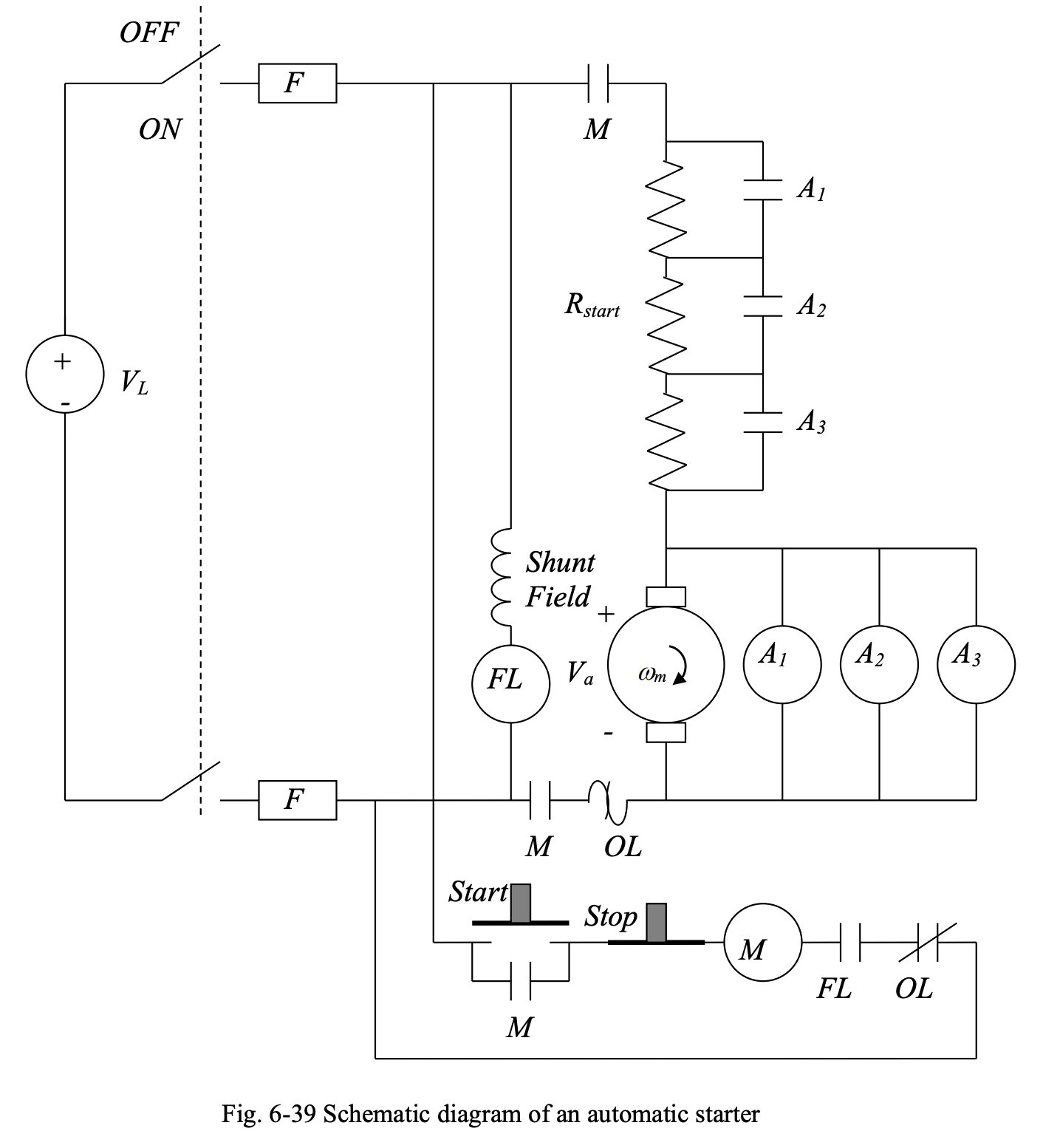
- When the main switch is turned on, the shunt field is energized, activating the field loss (FL) contactor, such that the normally-open (NO) contact is closed.
- As long as there is no overload in the motor, the overload (OL) relay does not operate and the normally-closed (NC) contact remains closed.
- When the start button is pressed, is is applied to contactor . Upon energization of , all NO contacts will close. This connects power to the armature.
- As long as motor speed is low, back emf is small, and contactors , and are not energized and the NO contacts , and remain open. Therefore, the whole is in series with the armature, and is limited.
- As the motor accelerates, at different speeds, corresponding to different back emf values, contactors , , will be energized in turn and the NO contacts , and will be closed in turn, short circuiting segments of , letting the motor speed up at a safe armature current value.
- , the field loss contactor, protects against the motor against loss of field, which results in overspeed.
Note that we have:
If for some reason, during the operation of the motor, the field is lost, i.e., =0, the flux will drop to the small value of residual flux, and will rise to dangerously high values. In this case, the contactor will operate, and the closed contact will open to shut down the motor.
To stop the motor, one must disconnect power by pressing the stop push button to de-energize contactor and open contacts.