The simple DC generator has two distinct shortcomings:
- The magnitude of the output voltage is low.
- The output voltage is not a smooth DC and has high ripple content.
The magnitude of the output voltage can be increased by increasing the number of coils of wire on the rotor and connecting them in series.
Operation
Figure 6-7 shows a 4-loop, 2-pole DC generator with two parallel paths between the output terminals, each composed of two series-connected loops of wire:
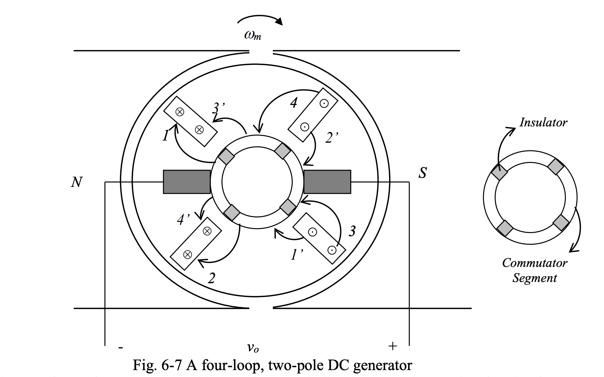
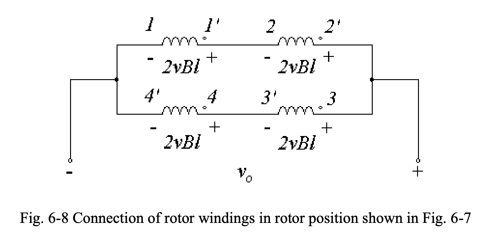
Initial Position
Fig. 6-8 shows the connection of loops of rotor winding between the two brushes for the rotor position shown in Fig. 6-7, together with the voltages induced in each loop. Note that for this rotor position, all loop sides are under the pole faces; therefore, each the loop develops a voltage of . As a result, the output voltage will be .
As the rotor turns through :
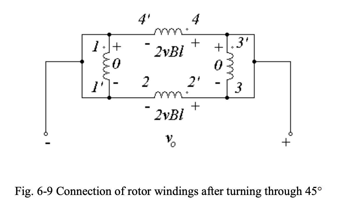
- Loops 1-1’ and 3-3’ fall out of the pole faces, with zero voltages induced in them, and will be short-circuited by the brushes.
- Loops 2-2’ and 4-4’ will stay under the pole faces and each will produce a voltage of .
- The connection of the loops of rotor winding, in this case, is shown in Fig. 6-9. Note that the output voltage will be .
As the rotor turns through another , the connections of the loops of rotor winding will change to:
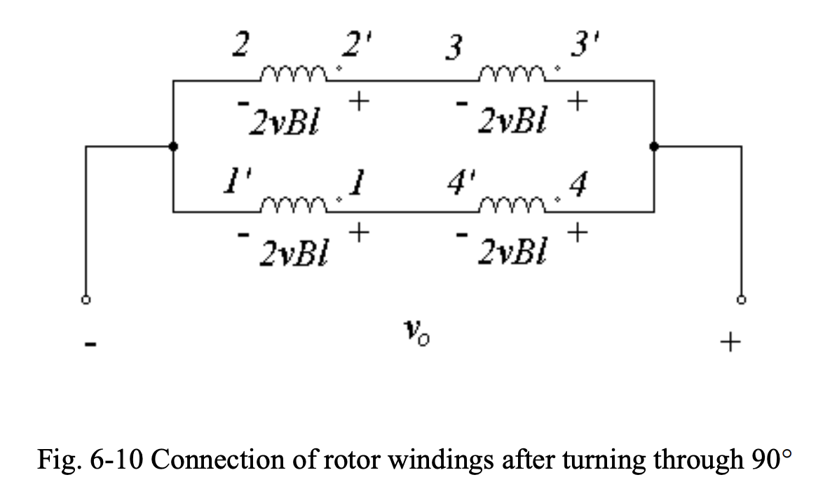
- All loop sides are under the pole faces, so a voltage of will be induced in each loop.
- Even though the voltages induced in two of the loops have opposite polarities with respect to those of the original position in Fig. 6-8, due to commutation the same voltage polarity at the output terminals is obtained.
- Thus, the output voltage will be .
As the rotor rotates through another , the connections of the loops of rotor winding takes the configuration shown in Fig. 6-11.
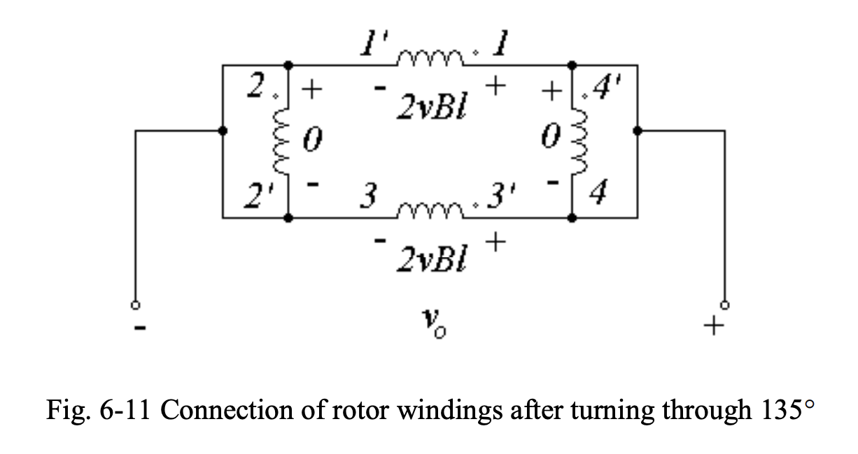
- Since loops 2-2’ and 4-4’ leave the pole faces, the voltages induced in them will be zero.
- The voltages induced in loops 1-1’ and 3-3’, which stay under the pole faces, will be equal to 2vBl each.
- Therefore, the output will be .
As the rotor turns through another with respect to the original position shown in Fig. 6-7), the connection diagram of the rotor loops will change to that shown in Fig. 6-12.
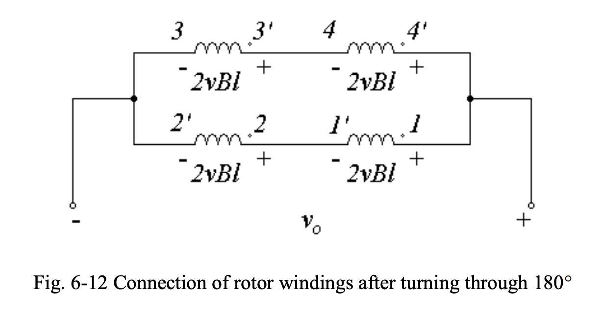
- With all four loops under the pole faces, the voltage induced in each loop will be 2vBl with a negative polarity. However, due to commutation, the output voltage polarity will not change.
- The output voltage in this case is .
Behavior + Notes
The output voltage waveform will be as shown below.
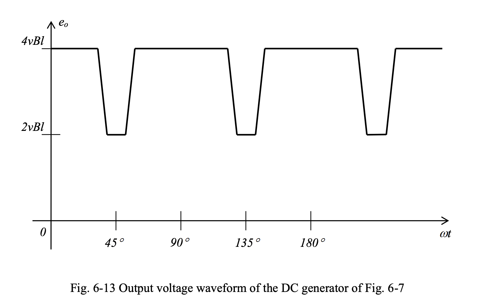
Observe that:
- In the four-loop, two-pole DC generator, as the rotor completes half a revolution (), the voltage induced in each loop goes through a complete cycle
- In the single-loop generator, it takes one revolution of the rotor () for each loop voltage to complete one cycle.
This means:
- The frequency of the variations in the output voltage has doubled, causing output voltage excursions to be between and , instead of between and , leading to lower ripple contents.
- The output voltage amplitude has doubled as a result of using two loops in series in each of the two parallel paths in the rotor winding.
- Due to connecting the two loops in parallel (providing two parallel paths), the current carrying capability of the machine is two times that of the single-loop machine.
Thus, by using more loops in series and parallel, the power rating of the generator can be increased and the ripple of the output terminal voltage reduced.
Increasing Poles
Another way for increasing the frequency of repetition, resulting in reduction of output voltage ripple content, is to increase the number of poles on the stator.
To understand the relationship between the number of poles and frequency of repetition, we need to develop the relationship between the electrical angle, which is associated with the variations in the output voltage, and mechanical angle, which is associated with the position of the rotor.
- In a 2-pole machine, we have .
- In a 4-pole machine, we have where is the number of poles on the stator.
Thus:
- In a 2-pole machine, the loop sides are 180 mechanical degrees apart (or 180 electrical degrees apart)
- In a 4-pole machine, the loop sides are arranged to be 90 mechanical degrees apart (but still 180 electrical degrees apart).
- In a -pole machine, the loop sides are arranged to be mechanical degrees apart (but still 180 electrical degrees apart).