The emf generated in the loop of a simple generator is inherently alternating, as previously shown. In a DC generator, it is required to produce a DC voltage at the output terminals. The AC-to-DC conversion is performed via the mechanism of commutation.
Helpful video: Working Principle of DC Generator
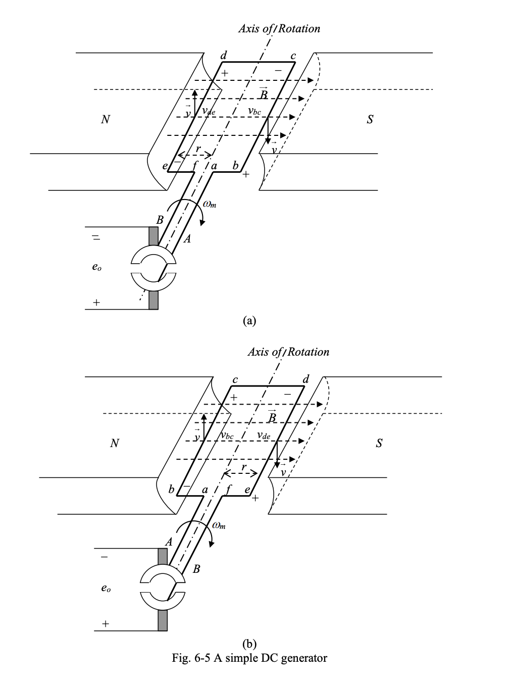
The figure below shows the simple generator, where two semicircular conductive pieces called commutator segments have been attached to the two leads of the loop. These two segments turn with the loop. The commutator segments rub against two stationary carbon brushes to which the terminals of the generator are connected.
Operation
(Current flows from to ).
Basically, the idea is that if we focus on the current in a given piece of the loop in the AC generator, like bc, it will change directions halfway through.
- In part (a) of the diagram below, current will flow from b to c.
- In part (b), current now flows from c to b.
- Using commutators, we keep the terminals consistently attached to one direction of current flow (positive terminal has current flowing away from it, negative terminal has current flowing into it), so that there is no switching of current direction from the perspective of the terminals.
- The commutator reverses the connection to the brushes at the exact moment the current in the loop segment reverses. This ensures that the current in the external circuit always flows in the same direction.
Detailed Walkthrough
As the loop rotates, for the first , when loop sides bc and de are under the south and north poles respectively:
- The brush connected to the positive output terminal is in contact with the commutator segment attached to loop side bc.
- The brush connected to the negative output terminal is in contact with the commutator segment attached to loop side de.
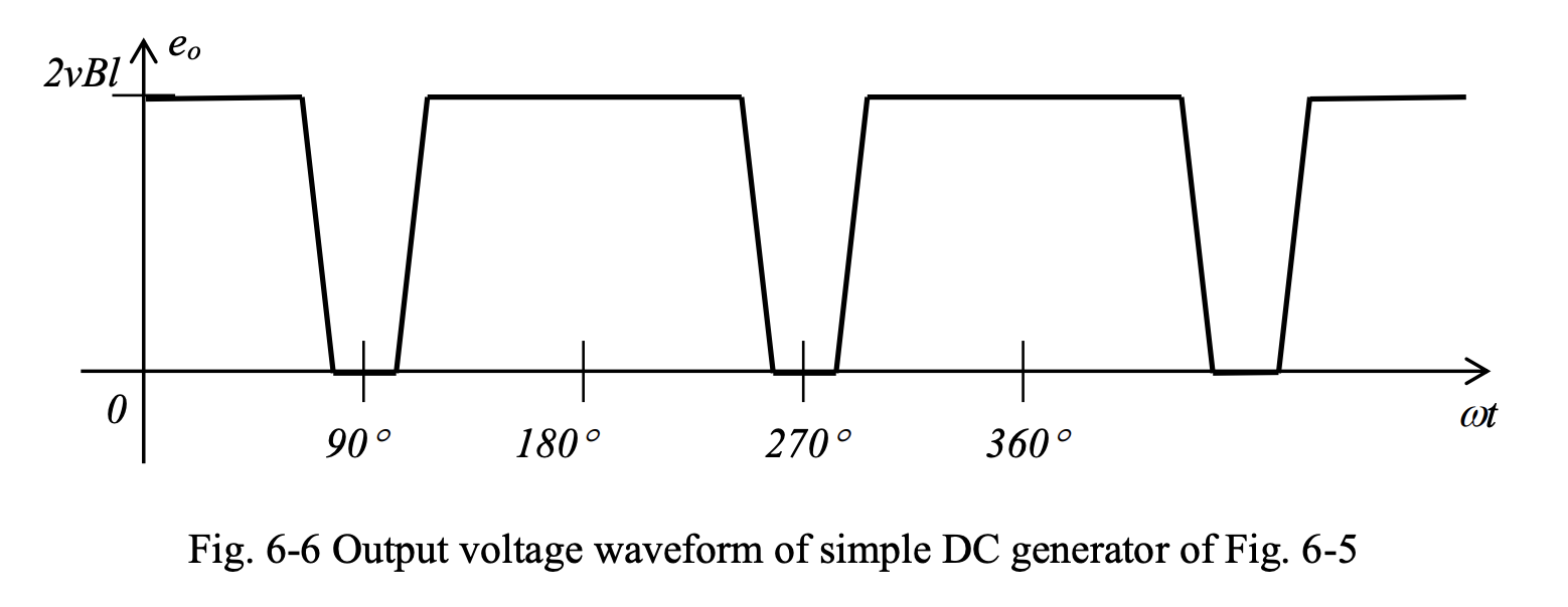
As the loop rotates and the loop sides leave the pole faces, the brushes short circuit the commutator segments, and the emf induced in the loop passes through zero.
During the next , when the loop sides bc and de are under the north and south poles:
- The brush connected to the positive output terminal will come in contact with the commutator segment attached to the loop side de.
- The brush connected to the negative output terminal will come in contact with the commutator segment attached to the loop side bc.
Therefore, as the loop rotates, the output voltage will assume the waveform shown below. This is a rectified version of the simple AC generator.