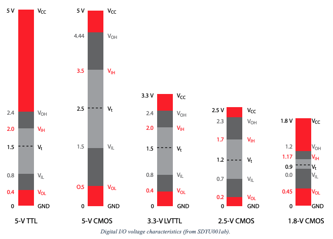
Many sensor modules use digital interfacing, but with different voltage levels. For example, a typical microcontroller like STM32 might use while an Arduino uses .
Device digital inputs and outputs conform to a standardized set of acceptable values called a “logic family”.
- On the driver side, is the output high voltage and is the output low voltage expected from the digital circuit.
- On the receiver side, is the input high voltage that indicates a digital
1. is the input low voltage, and is the maximum allowable voltage that indicates a digital0.

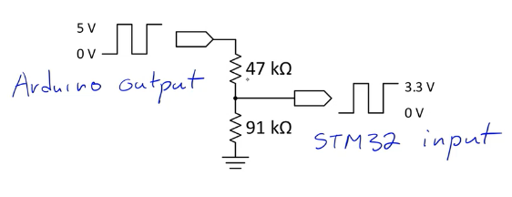
Step-Down Voltage Interfacing
A simple voltage divider is sufficient if your signal is one-directional and the driver outputs a higher voltage than the receiver can handle.

- Recall that GPIO inputs appear as capacitors, and will form RC time constant with divider resistors.
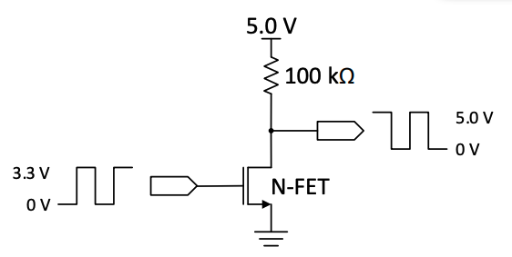
Step-Up Voltage Interfacing
We use a N-channel MOSFET with a pull-up resistor.The example below steps-up from 3.3 V to 5.0 V.
- There will be a rise time set by the and input capacitance. The value can be lowered to increase the maximum frequency of the digital signal at the cost of increased static power when the MOSFET is conducting.

Bidirectional Voltage Interfacing
A simple circuit that translates digital signals from one level to another is shown. It uses an N-channel MOSFET. The MOSFET drain (D) connects to the higher voltage signal (e.g. 5V signal from a device pin), and the source (S) connects to the lower voltage signal (3.3 MCU pin). This circuit operates bidirectionally but can only be used for digital signals, not analog signals.