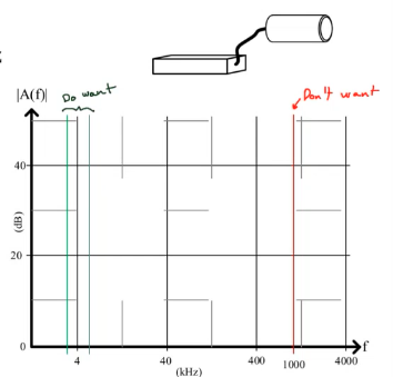
You have a sensor operating at 4 kHz +/- 1 kHz connected to a data acquisition circuit you’re designing. It is powered by a boost converter that takes low voltage and uses an inductor to boost the voltage to a higher working voltage. The boost converter activated the inductor at a rate of 1 MHz.
Design a filter that provides 100x gain (40 dB) and eliminates the switching noise from the boost converter.

Two-stage Solution
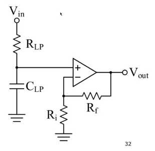
We want to pass lower frequencies, so we can add a low-pass filter and then add an op-amp for gain:

For phase 1, it’s a voltage divider so:
For phase 2:
In total, we have .
- If we choose , we can choose AND .
- We can also choose so we can choose some values for that.
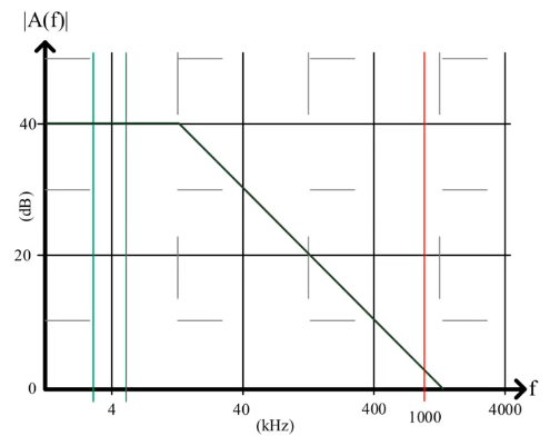
The plot looks like:
One-stage Solution
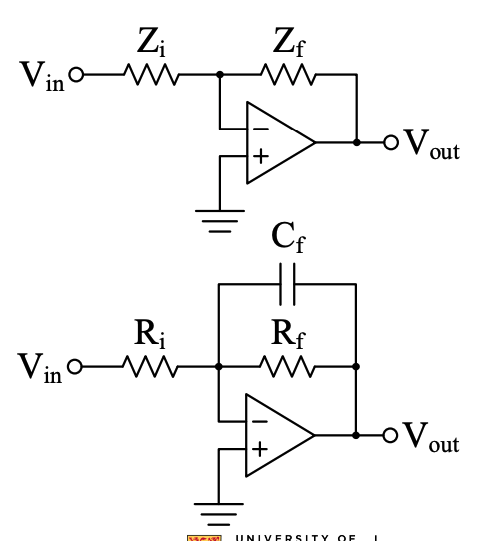
Or we can do everything together:

We have . We want until , then drop:
- Set
- Set (give a little extra room since there’s actually -3 dB right at the cutoff frequency)
- To make go to zero as increases, we want or
Starting from , we then have:
(Note that in the final expression, is just , where ).
Thus, we becomes:
Choosing gives us . For the capacitor, we have:
Bode Plot
The resulting Bode magnitude plot is:
