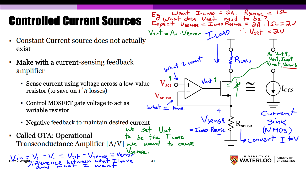
Controlled current sources do not actually exist. They are made using a current-sensing feedback amplifier.
The current is sensed using voltage across a low-value resistor (to save on losses). A control MOSFET gate voltage acts as a variable resistor. Negative feedback is used to maintain desired current.
We provide a fixed amount of current applied to some load (modeled as ). Op-amps can’t sense current, but we can find a known voltage, using . Fundamentally, the op-amp finds the difference between its two terminals, which is essentially the difference between what we have and what we want:
Then, the output signal given by the op-amp, , is just the .
So, we set to be the that we want to cause . For example, if we want , and have , then what would need to be?
Therefore, if we set to get an of .
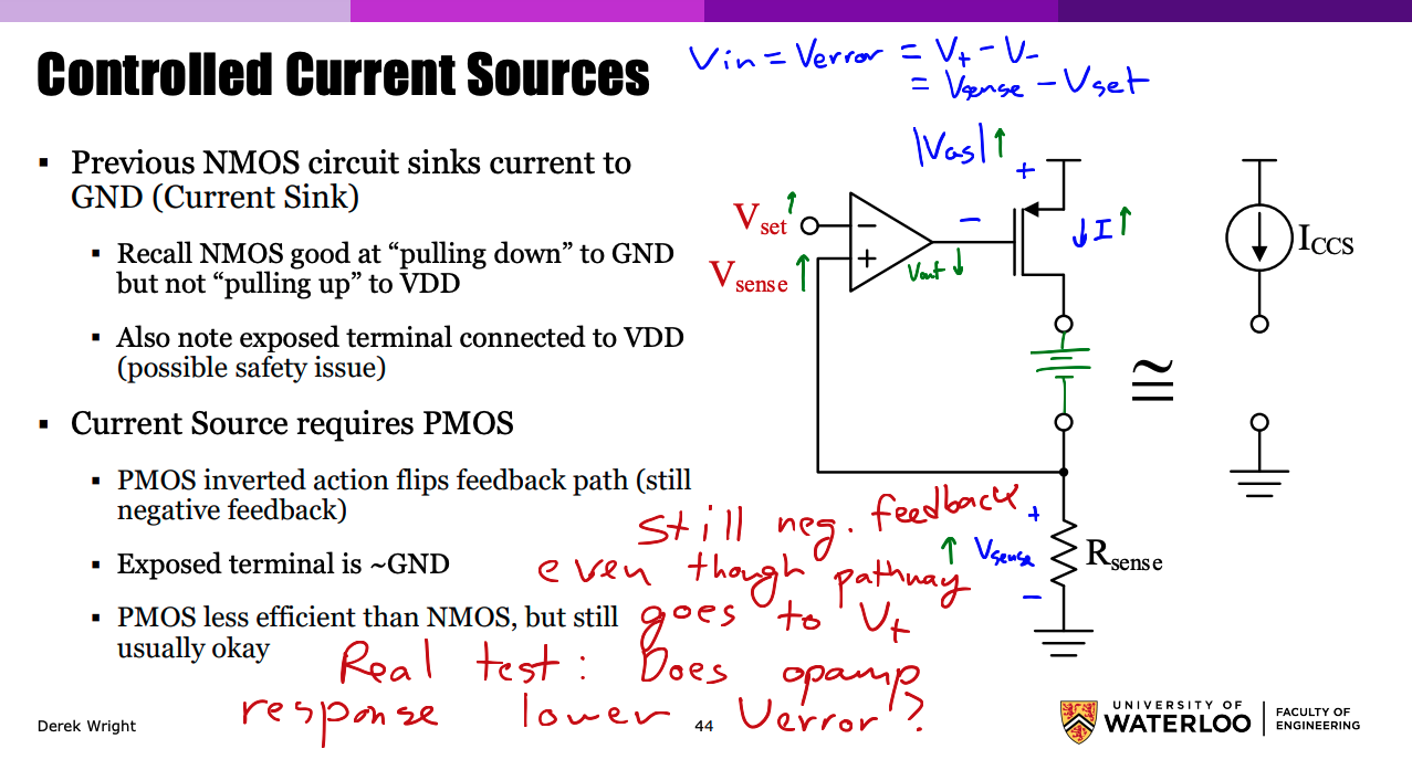
Following the concepts of negative feedback: As increases, goes up, and goes up, so goes up and decreases.
Example
Design the circuit above to charge a 14.4 V rechargeable battery, given:
- from to
- An MCU DAC can generate from 0 to
A way we can find is to consider the max values of the problem:
What about power? This dissipates . We can let be much lower (depending on how noisy things are). Derek Wright decrees that for this problem we will choose an E24 resistor (divide by 10), which still gives of signal, so that . For an actual problem, more information should be included so that we can make educated decisions on trade-offs between noise, power, etc based on the specific application at hand.
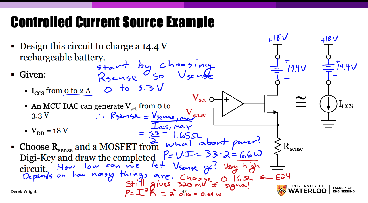
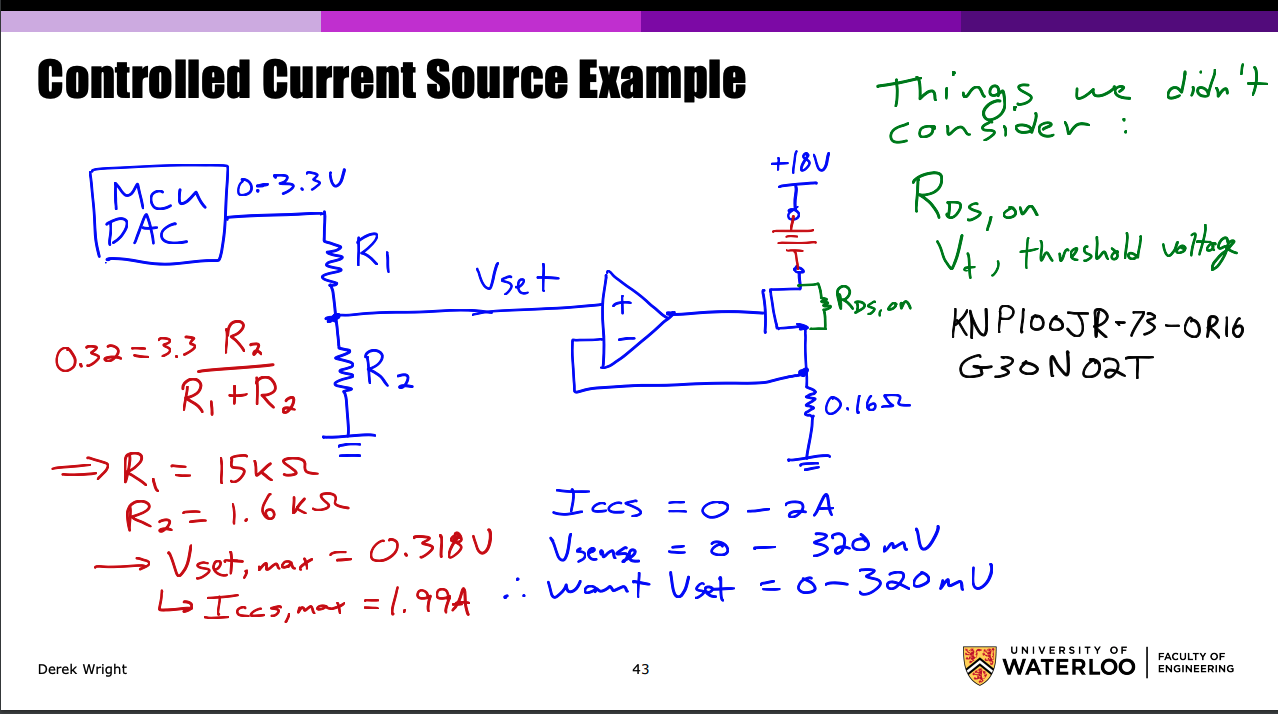
We find by making a voltage divider given of signal.
Alternate Configuration
If we want to use a PMOS instead of an NMOS (for example safety issue of terminal connected to , whereas using a PMOS would expose ground), we can use the pMOS inverted action to flip the feedback path so that we still get negative feedback. This is less efficient, but generally still okay.