Operating Principle
The fundamental operating principle of induction motors relies on electromagnetic induction, where a change in magnetic flux induces an electromotive force (EMF) and consequently generates an electric current in a conductor.

In the diagram above, a rotating coil is shown to be interacting with a rotating magnetic field. Assume that both the magnet and the coil are rotating CW, with the magnet moving at a little higher speed than the coil.
- The rotating magnetic field created by the magnet is represented as , changing over time to .
- The time-varying magnetic field induces an electric field within the coil.
Note that the rotating magnetic field can be replicated by supplying a sinusoidal electrical field (AC power) to the fixed coil.
As the magnet rotates faster than the coil, from the coil’s perspective, it appears as though it is rotating CCW relative to the fixed magnetic field. This relative rotation induces a current in the coil according to the Fleming’s right-hand rule of generators.
The induced current in turn generates a force on the coil that tends to keep it rotating in the original clockwise direction, as explained by Fleming’s left-hand rule of motors.
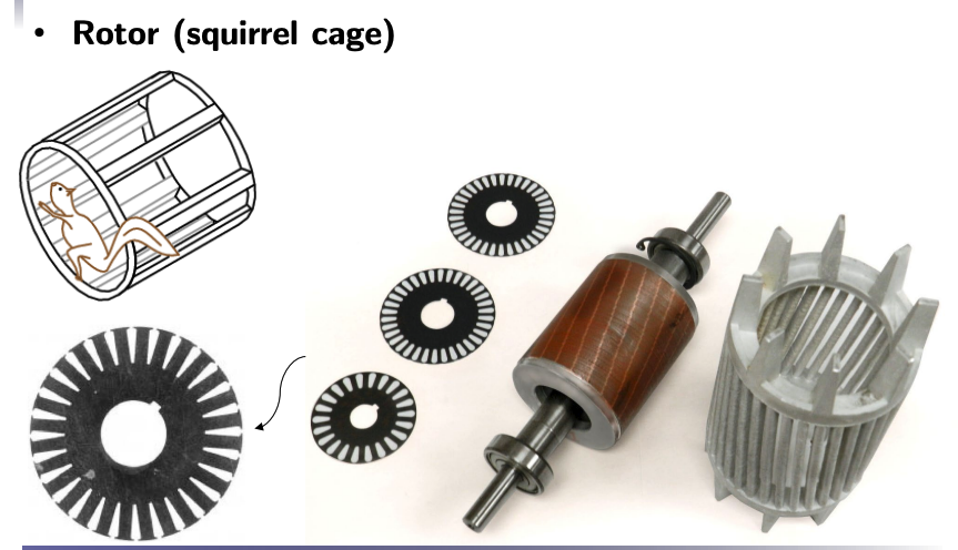
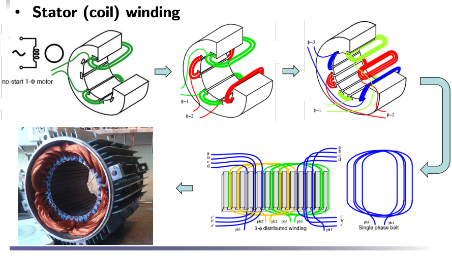
Construction of Induction Motor


3-Phase Induction Motors
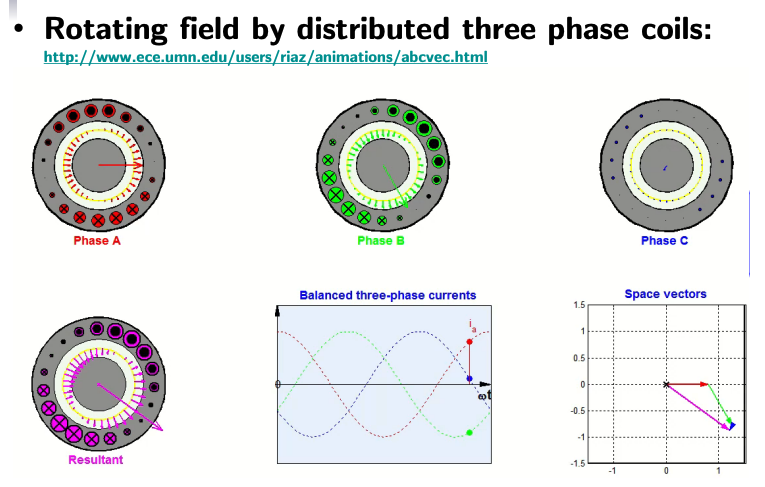
Three-phase AC power is used to create a rotating magnetic field in an induction motor. Specifically, each phase is connected to separate windings arranged around the stator of the motor. Phase A produces a magnetic field shown in red, Phase B generates the green magnetic field, Phase C generates the blue magnetic field.
Each phase’s magnetic field is generated with a 120-degree phase difference relative to the others, ensuring a continuous and smooth rotation of the resultant magnetic field. The resultant magnetic field is shown in purple. This field moves continuously around the stator, inducing currents in the rotor and creating torque, thus driving the motor.
