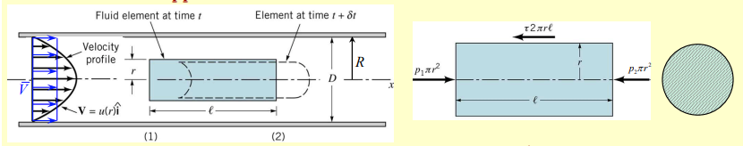
To analyze a fluid element flowing through a cylindrical pipe under fully developed laminar flow, we apply Newton’s Second Law to a cylindrical volume of fluid.
In the fully developed laminar flow, The pressure difference () across the length () of the fluid element creates a net driving force. This pressure force is balanced by shear stress acting on the walls of the pipe.
This force balance is written as
where is the radius at any point within the pipe, is the length of the cylindrical element, and is the shear stress.
The relationship rearranges to express shear stress as a function of the radius:
which shows that shear stress linearly proportional to the radius . The constant is introduced to express shear stress independently of . At the centerline, , which gives
At the pipe wall, ,
showing that shear stress indeed reaches its maximum value of .
We can also connect the maximum shear stress at the wall to the overall pressure drop along the pipe’s length:
Velocity Profile Derivation
The velocity profile for fully developed laminar flow is derived from the derivation of shear stress in terms of velocity gradient:
or
This equation represents a parabolic boundary profile. We can use and as boundary conditions:
where is the maximum velocity, occurring at the centerline.
The velocity profile at any point is then by:
Flow Rate Calculation
The volumetric flow rate is determined by integrating the velocity profile across the pipe’s cross-sectional area:
This represents the volume of fluid passing through the pipe per unit time. The average velocity is defined by the flow rate divided by the cross sectional area:
In this way we can also write the pressure drop over a given pipe length as
Darcy Friction Factor
For laminar flow, the Darcy Friction factor quantifies the friction resistance
or
For fully developed laminar flow in a pipe, the friction factor simplifies to: