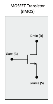
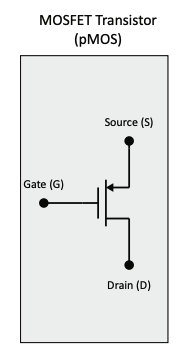
The most common transistor logic family used to build circuit is complementary metal oxide semiconductor (CMOS). The transistor model used in MTE 325 has three connections: gate, source, drain. CMOS transistors are controlled by the gate and current flows between the source and drain.
The transistor is modeled as a switch. A transistor that is “on” acts like a short circuit between the source and drain, while one that is “off” can be modeled as an open circuit between the source and drain.
NMOS
A simple digital model of an NMOS transistor:
- If the input voltage () is a logic 0, the NMOS transistor is modeled as an open circuit between source (S) and drain (D).
- If the input voltage () is a logic 1, the NMOS transistor is modeled as an closed circuit between source (S) and drain (D).

PMOS
A simple digital model of an PMOS transistor:
- If the input voltage () is a logic 1, the PMOS transistor is modeled as an open circuit between source (S) and drain (D).
- If the input voltage () is a logic 0, the PMOS transistor is modeled as an closed circuit between source (S) and drain (D).
