We can consider driver implementation by going past digital logic to think about the electrical fundamentals.
Input and Output Drivers
At a high level, there are two types of drivers:
- An output driver sends signals onto the bus or data line by sourcing or sinking current.
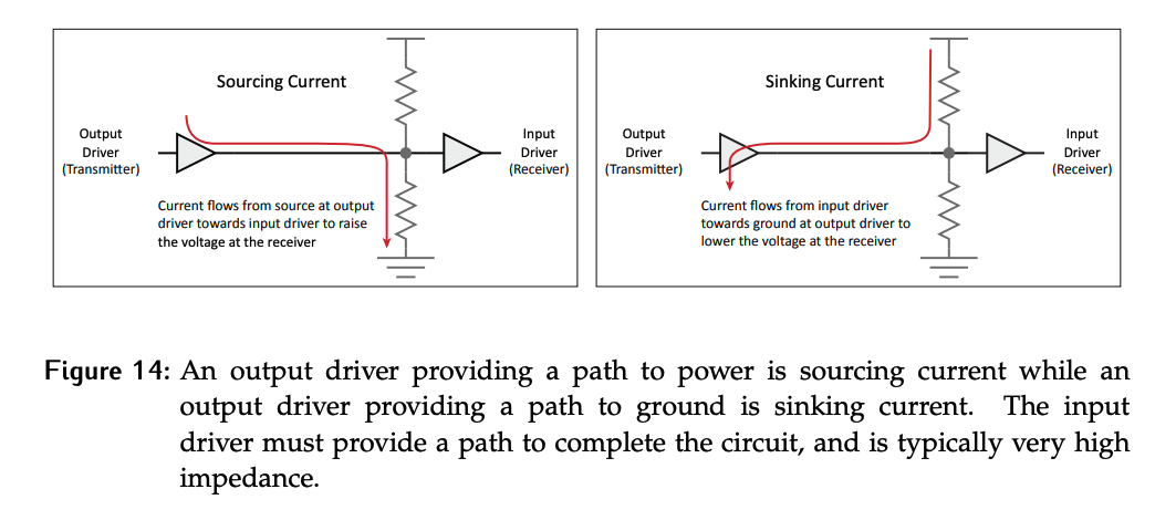
- Sourcing current means that the current flows from the output driver towards the input driver, raising the voltage at the receiver end.
- Sinking current means that current flows towards ground at output driver to lower the voltage at the receiver.
- An input driver receives signals from the bus or data line by reading voltage levels created by the output driver.
Current flows in the lines when a transition between values occurs.
If the output driver is connecting to a logic 1, it sources current as shown in the left side of Figure 14. In order for it to set this value on the bus line, there must be a corresponding sink/ground connection on the input side. In this case, current will flow from the output driver to the input driver.
On the other hand, if the output driver is providing a connection to ground, it will be a current sink. The input driver must have a path to power to source the current; there needs to be some connection to the data line from a power supply. The path to power or ground provided by the input driver is very high impedance. Current can flow as needed to change the value on the line but there won’t be large current draws.
If the output driver is not active, it is in a high impedance state such that it does not provide a path to a voltage source or a voltage sink. Saying a driver is “sourcing” or “sinking” is assumed to be from the perspective of the output driver.
Active and Passive Drivers
Using a simple model of transistors as digital switches, the hardware that physically drives wires to logic 1 or logic 0 can be considered. In general, active electrical components are those that require a power source to operate. Active drivers are able to manipulate the signals such that when they provide a path for current flow, it will take precedence over a path through a passive element.
Passive electrical components do not require power to operate. A passive driver is “weaker” than an active one; if a passive component provides a conflicting signal path relative to an active component, the path through the active component will “win”. This was seen in transistor inverters:
- In the NMOS case, the inverter could be described as having a passive pull-up and active pull-down
- In the PMOS case, the inverter had an active pull-up and a passive pull-down.
- Whenever the active path was enabled (transistor on) it set the output voltage.
In general, any path through a transistor will be active, while any path through a resistor will be passive.