Serial systems send the data one bit at a time, and as a result timing is a critical part of determining how to interpret the incoming signal.
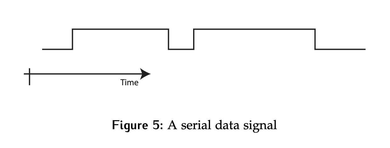
For a given serial data signal such as the one shown below, we need to figure out:
- How many bits are represented?
- What are their values?
- What do they mean?
The answer to all of these questions is there is no way to know with the information provided.
Bit/Byte/Block Synchronization
There are three levels of synchronization to successfully interpret a serial signal: bit, byte and block.
Bit Synchronization
Bit synchronization refers to the determination of the location of each bit for a serial data stream. How long is each bit? Where does it start and end? Bit synchronization includes:
- Bit rate synchronization: Determines the length of each bit and may be specified as a frequency (bits/second) or as a time per bit.
- Bit phase synchronization: Determines where the mid-point of the bit is in relation to either the local clock, or the clock transmitted with the data (depending on the protocol being used).
The easiest way to achieve bit synchronization is to use a synchronous protocol. In this case, the clock is transmitted with the data.
- The bit rate is set by the clock rate
- The bit phase can be set by agreement in the protocol. For example, the sender may change the data on each rising edge, while the receiver samples on the falling edge. If the duty cycle of the clock is 50/50, then the falling edge will correspond to the middle of the bit.
8-Byte Example
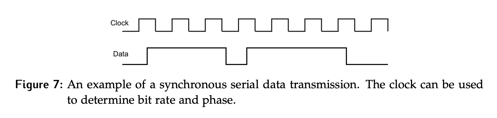
Consider a synchronous serial data transmission that consists of a data line and a clock signal as shown below in Figure 7.
- How many bits are represented? There are 8 clock cycles, and therefore 8 bits of data transmitted?
- What are the bit values? What the data values are depends on whether we use the rising or falling edge of the clock to sample the data. > - If the rising edge is used, the data is . > - If the falling edge is used, the data is . > - We don’t know which one is correct without additional knowledge of the protocol being used.
- What do the bit values mean? It’s impossible to say at this point without additional knowledge of the protocol being used.
16-Byte Example
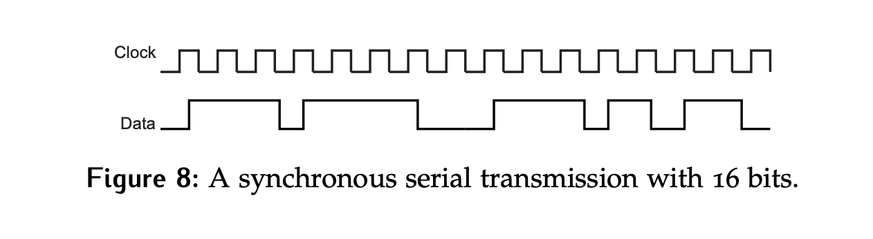
Consider the input signal and a clock as shown in Figure 8.
Assuming that bit synchronization has been established and that the receiver should sample on the rising edge of the clock, the bits can be reliably interpreted. In this case there are 16 bits - .
Byte Synchronization
How should the data in the example above (Figure 8) be read? This depends on how we define a byte boundary.
- If we assume a byte starts on the first bit, then the first byte will read , or
0x6E. - If we assume it starts on the second bit, the first byte will read , or
0xDC. - Starting on the third bit gives
0xB9, etc.
Thus, there has to be some convention established on where the byte starts, and what the bytes mean for the data to be useful. This is often done by adding a byte clock.
Byte Clock Example
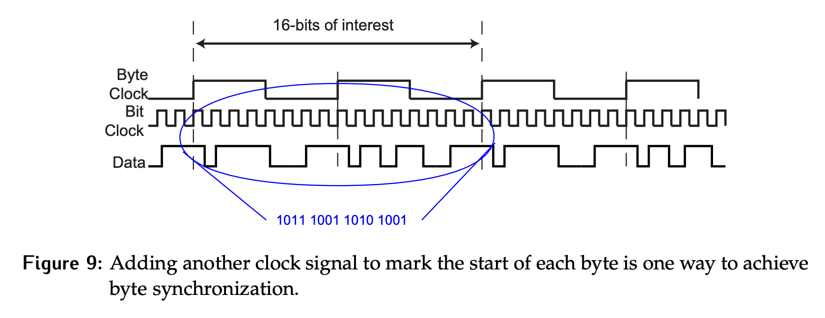
Consider the input signal and clock signals as shown in Figure 9.
- The clock (bit clock above) provides one way to get the bit timing. If it is assumed data is sampled on the rising edge, then bit synchronization has been attained and the bits can be reliably interpreted.
- In this example, a second clock signal (byte clock), with a frequency of 1/8 of the bit clock, has been added. The two clocks are phase-aligned on rising edges.
- This slower clock can be used to mark the byte boundary, with a new byte starting on each rising edge by agreement between the two sides.
- The bytes detected would be
0xB9followed by0xA9.- But what do the bytes mean? Are they raw data? ASCII characters? Are they part of a block? There is no way to know without additional information.