There are many arbitration schemes that do not use daisy chains to pass a grant signal. One based on a parallel evaluation of devices requesting the bus and one that takes a serial approach will be presented here.
Consider a monolithic arbitration system that receives requests from each device and is able to issue grants to each device as shown below in Figure 11.
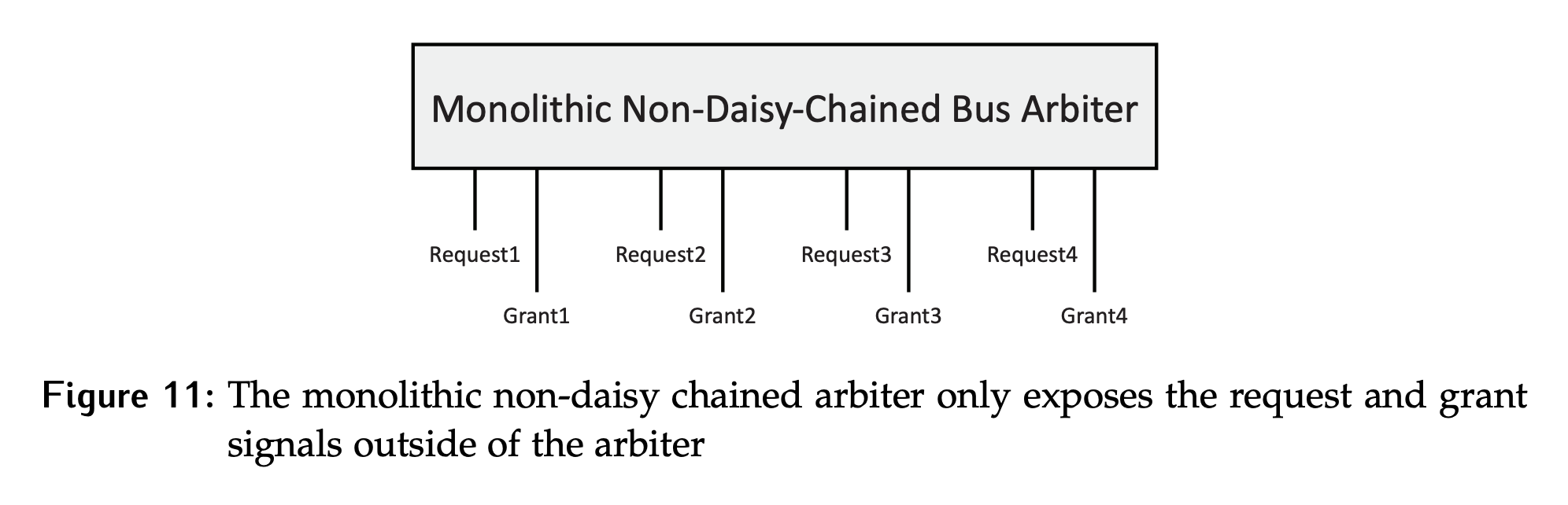
- Since this is an arbiter, only one grant signal will ever be active at a time, uniquely selecting the bus controller.
- The earlier assumption that the system is not pre-emptive is still in effect; so, once a device has control of the bus, it cannot be forced to give it up.
- The assumption that a device cannot change its mind about requesting the bus is also still in effect.
- Since this is a monolithic system, only a fixed number of devices are supported. Of course, fewer devices could be active at any given time.
The IEEE-696 standard was released in the early 80’s, and was quite common before it was deprecated, in the mid 90’s. While it is no longer an active protocol, the underlying ideas are still used in modern systems so it is worth taking a look at. This system takes a parallel approach to arbitration as shown in Figure 12. It makes use of some additional wires, which are also used for DMA.
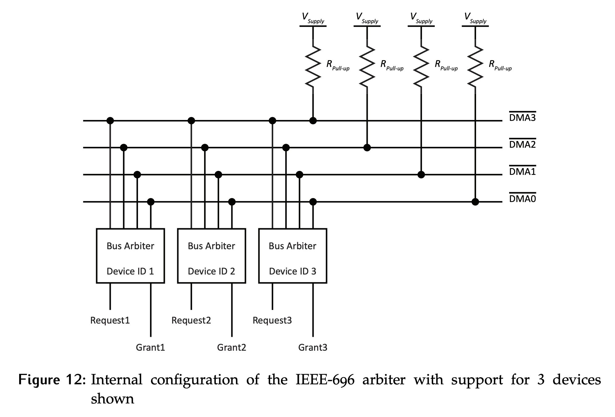
- Notice that the wires are active low and pull up resistors are used. This is a big hint as to the type of logic used by the drivers inside the arbiter. They are open-collector, which behaves the same as open-drain.
- Each bus arbiter has a unique 4 bit ID, with the ID of
0000being reserved for an idle bus. This leaves 15 ID numbers available for devices. The priority of the devices is fixed, with the highest ID having the highest priority.- During an arbitration cycle, all devices wishing to use the bus will assert the inverse of their ID on the shared lines at the same time. Remember that they are open-collector drivers, so this will not cause a conflict.
- The final value on the bus lines will be the complement of the ID of the device that has won the arbitration round, and a grant signal will be generated for that device only.
A simplified model of the logic inside each arbiter is shown in Figure 13.

- There is a control signal to indicate the start of an arbitration cycle. This is essential, otherwise a request from a higher priority device would result in the transfer of the grant to that device whether the device currently using the bus was done or not. Since there is a restriction of no pre-emption, this is not allowed.
- Notice that if it does not have a request, the output of the first set of AND gates will be 0000, which is the reserved ID for idle. If there is a request at the start of a cycle, it will drive the inverse of its ID.
- Caveat: There is a cascading logic between subsequently lower bits, so while all lines are driven at the same time, there will be a delay for the values to settle out.
- Starting from the MSB, the value is driven through an open collector inverter.
- This means if any device in the system is outputting a zero, it will dominate the passive 1 and be what is seen at the input to the leftmost OR gate.
- Since this is then NAND-ed with the next lower bit, the output of this driver depends both on the result of the arbitration for the MSB as well as the ID’s value in this bit position.
- Moving towards the LSB, notice that it is dependent on the results of the arbitration for all previous bits.