Metastability is a side effect of flip-flips that must be mitigated in embedded systems. Metastability occurs when setup or hold times on a flip-flop are violated, resulting in an unpredictable output. It could still be the old value, the new value, or an oscillating/unstable value. If this value is then used by other logic, such as combinational logic, it can lead to undesirable or strange behaviors.
What is the cause? Inside a D flip-flop, there is a pair of cross-coupled NAND gates, meaning that the output of one is fed back to the input of the other. Due to this feedback path, changing one of the NAND gate inputs while there is propagation ion the feedback paths can cause a race condition.
As a result, the behavior of the device is only guaranteed when the input changes of the sensitive time frames shown below.
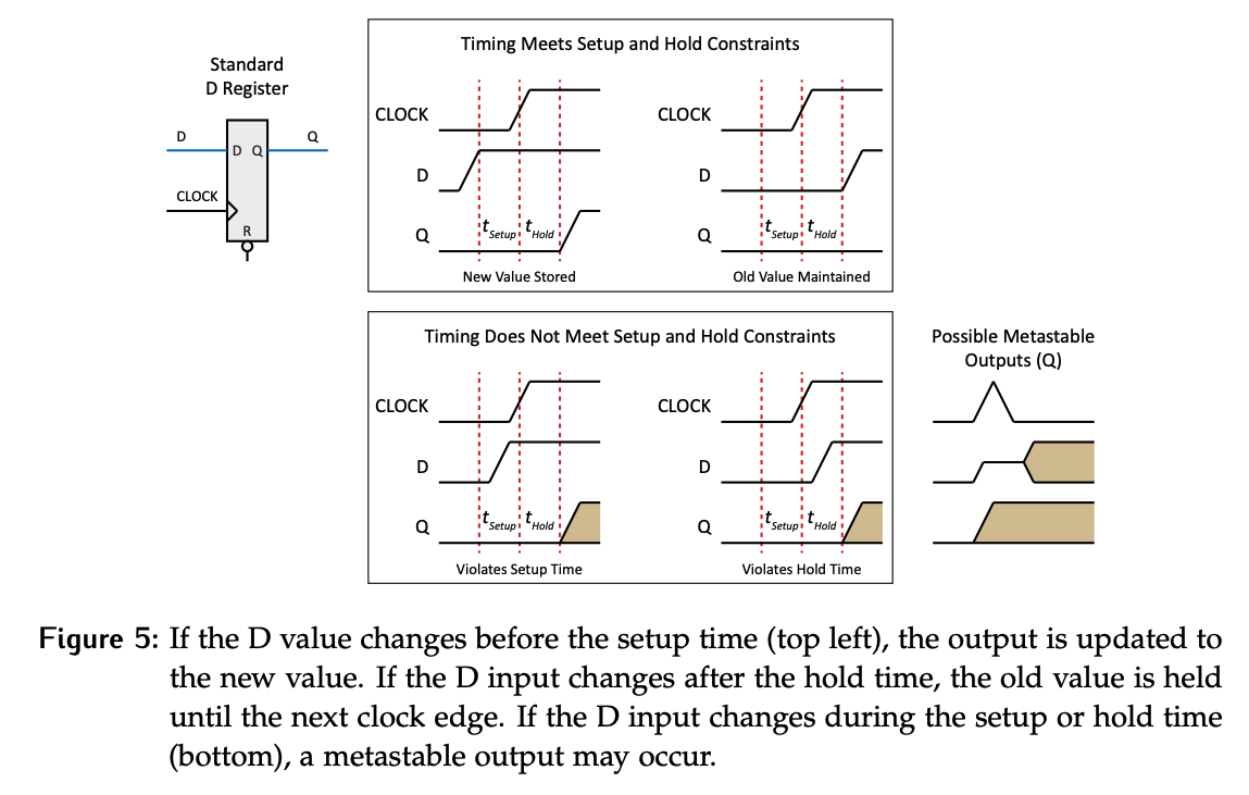
The critical time before the clock edge is the setup time, the time after the clock edge is the hold time. These times create a window during which the data input to the flow must not change.
- If the input changes before this time, the output will be the new value.
- If the input changes after this time, the output will be the old value until the next clock edge.
- If it changes during this window, we might have metastability.
Possible outcomes of metastability:
- Best case: Value updates as expected.
- OK case: Old value is held for one more cycle.
- Worse case: The result is an unstable value, which might settle to 1 or 0.
Solutions and Mitigations
The simple solution to removing metastability would be to not violate setup or hold times. Unfortunately, the possibility of metastability can never be fully eliminated. In embedded systems, it’s common for inputs to come from a source that has no knowledge of the timing of the system.
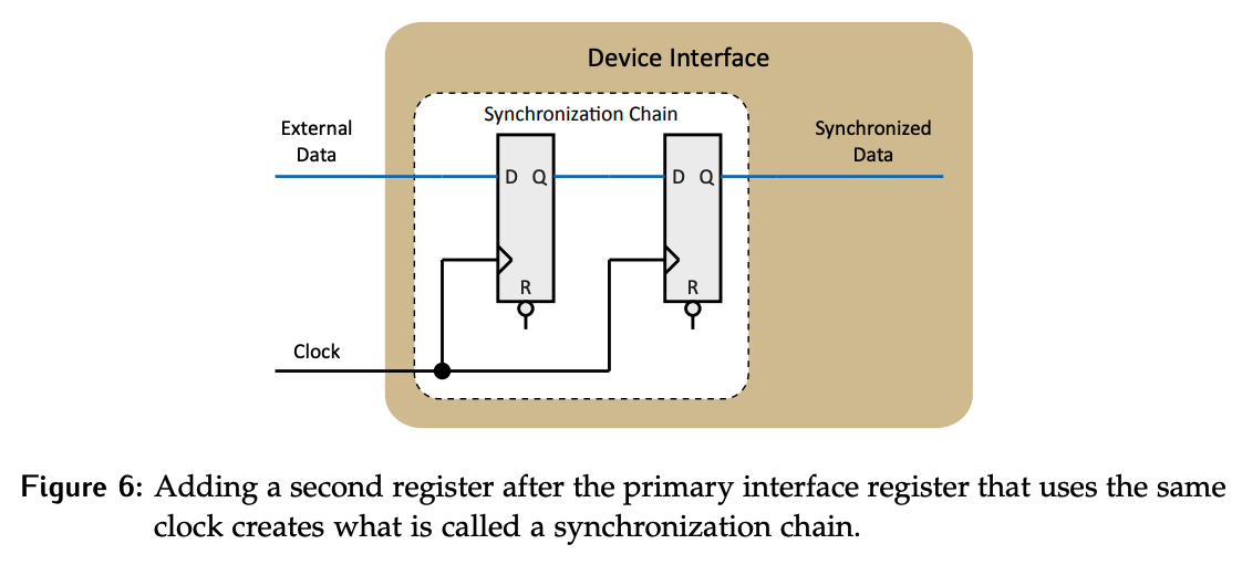
However, we can mitigate the negative effects of passing an unstable value by simply adding a second register with the same clock. This creates a synchronization chain. Unstable values can’t stay unstable forever and will eventually settle; as long as the time it may stay unstable is shorter than the time between clock edges, the possibility of unstable values reaching the downstream logic has been removed.
Example
Let’s say the external data input changes within the setup time of the clock edge and results in an unstable value at the output of the primary register.
- The synchronized data output holds
OldValueat this point. - The unstable value now settles. Let’s say it settles to
OldValue. - On the second clock edge,
NewValuegets clocked into the primary flop without any timing violations. The output of the second flop is stillOldValue. - On the third clock edge,
NewValuegets clocked into the second flop and is now available to the downstream circuit.
Flip-flop 2 just proves an additional layer of stability; it guarantees that there’s a stable value being sent to the rest of the system even if flip-flop 1 is unstable.
Adding the extra flop doesn’t guarantee the right value as soon as possible. Ideally, the output would have been updated after the second clock edge, but it does guarantee a stable value. That trade-off is worth it for the extra cycle it took the output to reach the final value.